
Electric power metering device with remote positioning function and working method thereof

A power metering device and remote positioning technology, which is applied in the direction of measuring devices, measuring electrical variables, measuring time integration, etc., can solve problems such as easy generation of more heat, inability to determine the location of power metering devices, and speeding up the aging speed of internal functional components.

Pending Publication Date: 2022-08-09
CHINA ELECTRIC POWER RES INST +1
View PDF0 Cites 0 Cited by
  • Summary
  • Abstract
  • Description
  • Claims
  • Application Information

AI Technical Summary

Problems solved by technology

[0003] However, in the prior art, due to the limitation of the actual structure of the existing power metering device, when the internal functional components fail, the operation of the equipment needs to be stopped, which affects the normal realization of the equipment functions, and makes the actual use effect of the equipment poor. At the same time, due to the protection requirements of the existing power metering device, the actual structure of the equipment is relatively sealed, and the long-term operation of the power equipment tends to generate more heat, which in turn tends to accelerate the aging of internal functional components under relatively dry and high temperature conditions, thereby affecting the actual performance of the equipment. At the same time, the actual position of the existing power metering device cannot be determined, which in turn affects the actual maintenance efficiency of the equipment and makes the actual use of the equipment less effective

Method used


Image

  • Electric power metering device with remote positioning function and working method thereof
  • Electric power metering device with remote positioning function and working method thereof
  • Electric power metering device with remote positioning function and working method thereof

Examples


Embodiment Construction

[0035] Exemplary embodiments of the present disclosure will be described in more detail below with reference to the accompanying drawings. While exemplary embodiments of the present disclosure are shown in the drawings, it should be understood that the present disclosure may be embodied in various forms and should not be limited by the embodiments set forth herein. Rather, these embodiments are provided so that the present disclosure will be more thoroughly understood, and will fully convey the scope of the present disclosure to those skilled in the art. It should be noted that the embodiments of the present invention and the features of the embodiments may be combined with each other under the condition of no conflict. The present invention will be described in detail below with reference to the accompanying drawings and in conjunction with the embodiments.

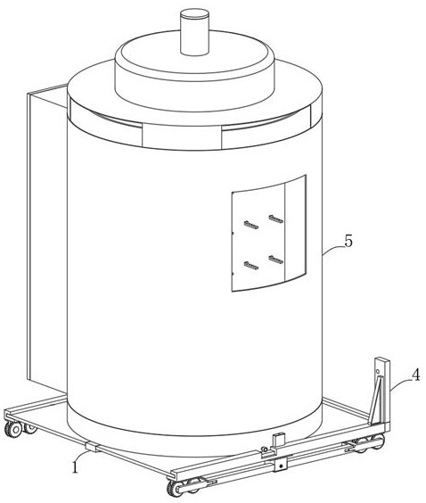
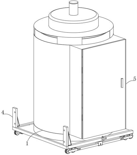
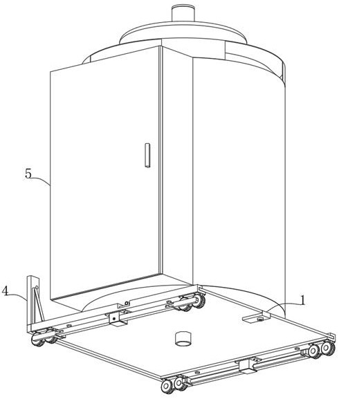
[0036] see Figure 1 to Figure 13 , which shows the preferred structure of the power metering device with the remote...


PUM


Abstract

The invention provides an electric power metering device with a remote positioning function and a working method thereof. The device comprises a moving mechanism; the supporting mechanism is arranged on the movable base and comprises a bottom frame, a limiting component and an adjusting component, supporting columns are arranged in the bottom frame in the circumferential direction, and a connecting base is arranged in the bottom frame; the carrier plate is arranged on the supporting mechanism; the connecting mechanism is arranged on the carrier plate; the storage mechanism comprises a storage frame and a heat dissipation positioning component, the storage frame is connected to the top of the bottom frame, and the heat dissipation positioning component is arranged on the storage frame. The first adjusting shaft is rotated to drive the threaded shaft to rotate through the first bevel gear, so that the threaded shaft can effectively eject the positioning rod, the ejected positioning rod can push the clamping plate to fix the position of the movable base, and the equipment can be stably placed at a specified use position; under the supporting of the supporting columns and the balls and the position limitation of the limiting grooves, the carrier plate can be effectively rotated and adjusted.

Description

technical field [0001] The present invention relates to the technical field of power equipment, and in particular, to a power metering device with a remote positioning function and a working method thereof. Background technique [0002] Electric power metering device is a measuring instrument used to measure and record power generation, power supply, factory power consumption, line loss power and user power consumption. It consists of a box, an electric energy meter, a circuit breaker, a current transformer, etc. [0003] However, in the prior art, due to the limitation of the actual structure of the existing power metering device, when the internal functional components fail, it is necessary to stop the operation of the equipment, thereby affecting the normal realization of the functions of the equipment, and thus making the actual use effect of the equipment poor. At the same time, due to the protection requirements of the existing power metering device, the actual struct...

Claims


Application Information

Patent Timeline
IPC IPC(8): G01R11/02G01R11/04
CPCG01R11/02G01R11/04Y04S20/30
Inventor 姜洪浪王晓东王爽段晓萌姜超赵婷宋虎聂晓阳左嘉陈方方
Owner CHINA ELECTRIC POWER RES INST
Learn More