
Checking jig for driving torque of small and micro motor

A technology of micro-motor and driving force, which is applied in the direction of torque measurement, electric components, and manufacturing motor generators, etc. It can solve the problems of unguaranteed detection accuracy, cumbersome and complicated operation, and low detection efficiency, and achieves simple structure and solution The effect of bulky, convenient fixing and clamping

Pending Publication Date: 2022-08-05
TIANJIN JOSEN TECH CO LTD
View PDF0 Cites 0 Cited by
  • Summary
  • Abstract
  • Description
  • Claims
  • Application Information

AI Technical Summary

Problems solved by technology

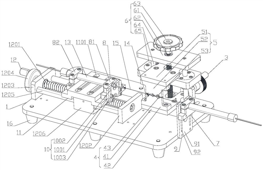
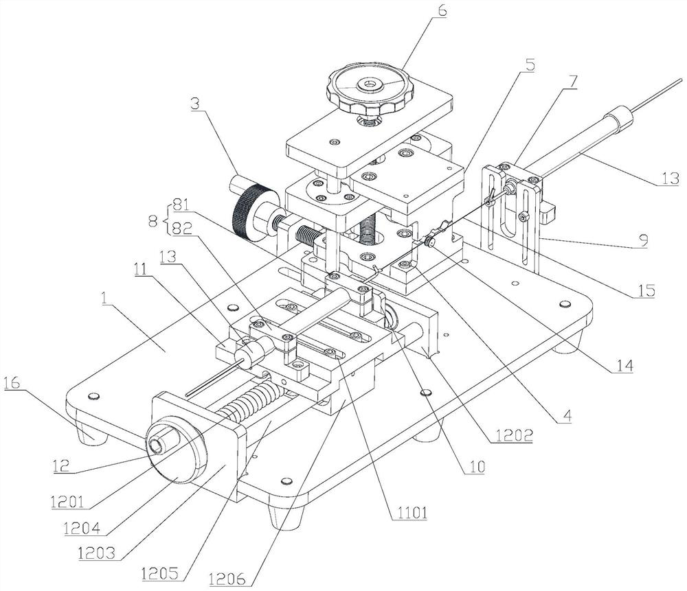
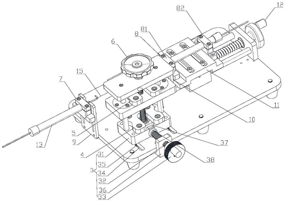
[0006] The purpose of the present invention is to provide a small and micro motor driving torque inspection jig, through the structural design of the small and micro motor driving torque inspection jig to solve the problem that the equipment for measuring the small and micro motor driving torque in the prior art is expensive and the operation is more cumbersome and complicated. The technical problem that the detection efficiency is low and the detection accuracy cannot be guaranteed

Method used


Image

  • Checking jig for driving torque of small and micro motor
  • Checking jig for driving torque of small and micro motor
  • Checking jig for driving torque of small and micro motor

Examples


Embodiment Construction

[0034] The technical solutions of the present invention will be clearly and completely described below with reference to the accompanying drawings. Obviously, the described embodiments are a part of the embodiments of the present invention, but not all of the embodiments. Based on the embodiments of the present invention, all other embodiments obtained by those of ordinary skill in the art without creative efforts shall fall within the protection scope of the present invention.

[0035] In the description of the present invention, it should be noted that the terms "center", "upper", "lower", "left", "right", "vertical", "horizontal", "inner", "outer", etc. The indicated orientation or positional relationship is based on the orientation or positional relationship shown in the accompanying drawings, which is only for the convenience of describing the present invention and simplifying the description, rather than indicating or implying that the indicated device or element must hav...


PUM


Abstract

The invention relates to a jig for checking the driving torque of a small and micro motor. Comprising a bottom plate, a first clamping mechanism and a second clamping mechanism are arranged above the bottom plate, the second clamping mechanism is fixed to the bottom plate through a Y-axis moving mechanism, the first clamping mechanism is connected with a Z-axis adjusting mechanism, and the Z-axis adjusting mechanism is fixed to the Y-axis moving mechanism; the device further comprises a fixed plate and a tension meter moving plate which are arranged on the two sides of the second clamping mechanism respectively, the fixed plate is fixed to the bottom plate through a first longitudinal adjusting mechanism, the tension meter moving plate is fixed to an X-axis moving plate through a second longitudinal adjusting mechanism, and the X-axis moving plate is fixed to the bottom plate through an X-axis adjusting mechanism. The fixed plate and the tension meter moving plate are provided with through holes, tension meters are respectively arranged on the through holes of the fixed plate and the tension meter moving plate in a penetrating manner, a rope is wound on the rope wheel, one end of the rope is connected with the tension meter fixed on the fixed plate, and the other end of the rope is connected with the tension meter fixed on the tension meter moving plate.

Description

technical field [0001] The invention relates to the field of motor detection fixtures, in particular to a small and micro motor driving torque detection fixture. Background technique [0002] Video conferencing and video surveillance equipment has the function of real-time steering movement in both horizontal and vertical dimensions. Standard specifications at all levels have high requirements on the rotation angle accuracy in both horizontal and vertical directions (including but not limited to noise control, energy consumption and efficiency, etc.) during the movement process, and the rotating module can be accurately positioned under working load conditions and Quick response is required, which lays the foundation for users to have a good experience in the use process. [0003] In the process of reproducing video conferencing and video surveillance equipment, the assembly and testing of motor drive modules are often not in the same process. The motor drive module cannot...

Claims


Application Information

Patent Timeline
Patent Type & Authority Applications(China)
IPC IPC(8): H02K15/14G01L3/00
CPCH02K15/14G01L3/00
Inventor 鲁浩袁亚伟徐荣光高嵩
Owner TIANJIN JOSEN TECH CO LTD
Learn More