
Fan pitching rotating shaft locking structure and fan with same

A technology of locking structure and rotating shaft, which is applied to components of pumping devices for elastic fluids, non-variable pumps, pump components, etc., can solve problems such as insecure locking, and achieve a simple and compact overall structure and easy assembly Simple, convenient and fast effect

Pending Publication Date: 2022-07-29
NINGBO SINGFUN ELECTRIC APPLIANCE
View PDF0 Cites 0 Cited by
  • Summary
  • Abstract
  • Description
  • Claims
  • Application Information

AI Technical Summary

Problems solved by technology

[0003] The purpose of this application is to address the deficiencies in the prior art, to provide a fan pitching shaft locking structure and a fan with this structure, which can solve the problem of insecure locking

Method used


Image

  • Fan pitching rotating shaft locking structure and fan with same
  • Fan pitching rotating shaft locking structure and fan with same
  • Fan pitching rotating shaft locking structure and fan with same

Examples


Embodiment Construction

[0019] The present application will be further described in conjunction with the following examples.

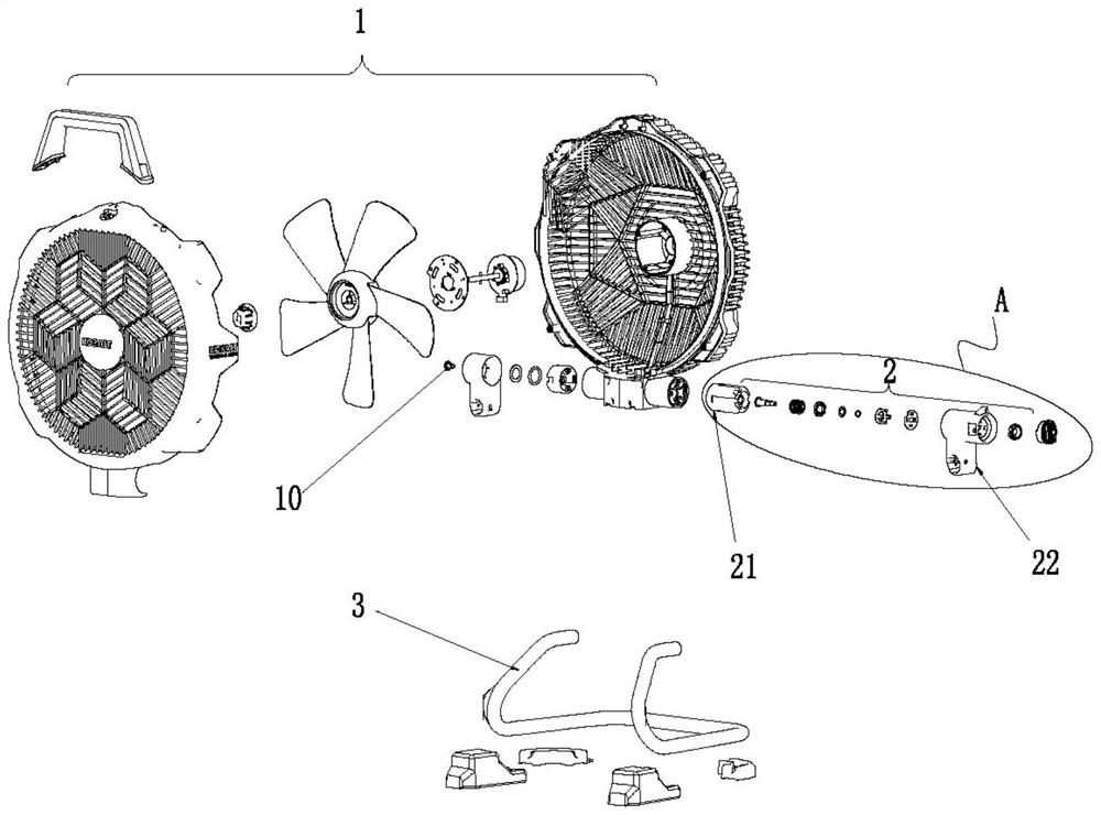
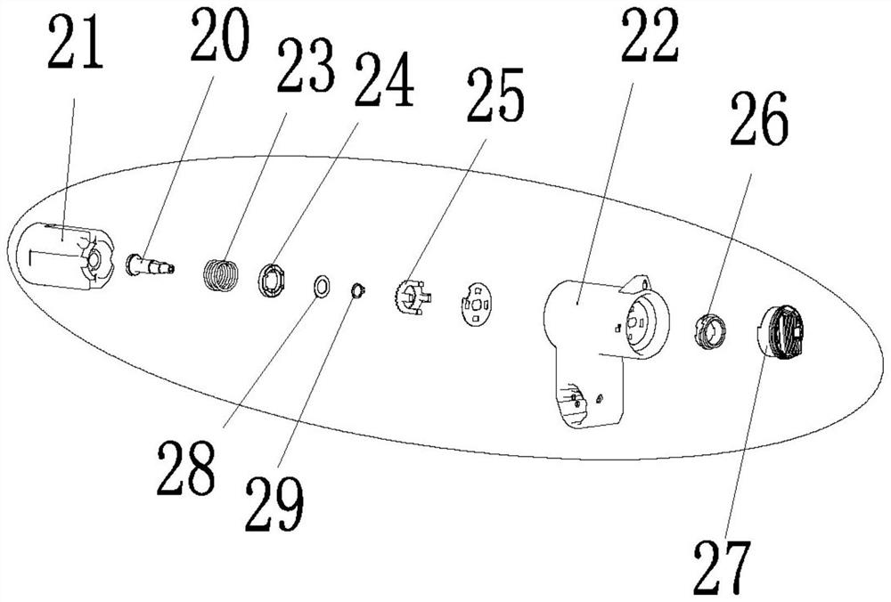
[0020] A specific implementation of a fan of the present application, such as Figure 1 to Figure 2 As shown, it includes a fan body 1 and a floor stand 3, and both sides of the fan body 1 are hinged on the floor stand 3 through hinge assemblies. The left and right sides of the fan body 1 are provided with rotating shafts 20 , and the rotating shaft locking structure of this embodiment can be set only on one of the rotating shafts 20 , and the relative rotation between the fan body 1 and the floor stand 3 can be realized only through the bearing 10 on the other side. .

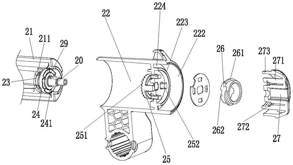
[0021] For the specific implementation of the fan pitching shaft locking structure of the present application, refer to figure 2 and image 3 , the locking structure includes a shaft seat 21 and a shaft housing 22 . The rotating shaft seat 21 is provided in a cylindrical shape, and the rotating shaft sea...


PUM


Abstract

The invention relates to a fan pitching rotating shaft locking structure and a fan with the same, the locking structure comprises a rotating shaft seat, a rotating shaft and a rotating shaft shell, the rotating shaft shell sleeves the outer side of the rotating shaft seat, and the rotating shaft is rotatably mounted in the rotating shaft seat; a limiting gear is arranged on the inner bottom face of the rotating shaft shell, a rotary knob is arranged on the outer top face of the rotating shaft shell and extends out of a barrel-shaped body towards the rotating shaft, the inner side face of the barrel-shaped body is in threaded connection with a rotating shaft threaded piece, and the limiting gear penetrates through the rotating shaft shell to be clamped with the rotating shaft threaded piece. The limiting gear can slide in the axial direction of the rotating shaft shell. The locking device is simple and compact in overall structure, high in stability and firm in locking effect.

Description

technical field [0001] The present application relates to a fan pitching rotating shaft locking structure and a fan having the structure. Background technique [0002] In order to facilitate the adjustment of the blowing angle of the fan, the existing fans are equipped with a pitch structure. Taking a floor fan as an example, the fan includes a fan body and a floor stand, and the fan body is hinged with the floor stand through a rotating shaft to realize pitch adjustment. In order to lock the blowing angle of the fan, the existing pitch structure uses a screw to tighten the top of the rotating shaft, so that the rotating shaft cannot rotate, so as to lock the main body of the fan. This type of screw generally has a plastic knob, and a screw is fixed to the side of the plastic knob, and the screw passes through the rotating shaft of the main body of the top fan. However, the structure of locking the rotating shaft by local interference is easy to lose the locking function d...

Claims


Application Information

Patent Timeline
Patent Type & Authority Applications(China)
IPC IPC(8): F04D29/00F04D27/00F04D29/64
CPCF04D29/002F04D27/00F04D29/646
Inventor 党信波谢海兵戴兆平姚裕初况永远徐亚黄刚卢以勒屈家宝
Owner NINGBO SINGFUN ELECTRIC APPLIANCE
Learn More