
Full-function cleaning base station

A clean-based, full-featured technology, applied in the field of cleaning base stations, can solve problems such as the general cleaning effect of cleaning robots and the reduction of the practicability of cleaning base stations

Pending Publication Date: 2022-07-29
麦岩智能科技(北京)有限公司
View PDF0 Cites 0 Cited by
  • Summary
  • Abstract
  • Description
  • Claims
  • Application Information

AI Technical Summary

Problems solved by technology

[0004] The purpose of the present invention is to solve the maintenance of the cleaning robot by the traditional cleaning base station in the prior art and the general cleaning effect. The shortcomings of the practicability of the clean base station are reduced, and the proposed full-featured clean base station

Method used


Image

  • Full-function cleaning base station
  • Full-function cleaning base station
  • Full-function cleaning base station

Examples


Embodiment 1

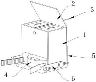
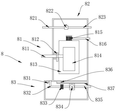
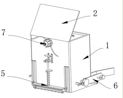
[0044] Example 1, as Figure 1-8 As shown, the present invention provides a full-function cleaning base station, including a case 1 and a limit structure 5, the upper end of the case 1 is rotatably connected with a cover plate 2, the rear side of the case 1 is electrically connected with a wire 3, and the interior of the case 1 is provided with The cleaning robot 4, the case 1 and the limiting structure 5, the upper end of the case 1 is rotatably connected with the cover plate 2, the rear side of the case 1 is electrically connected with the wire 3, the interior of the case 1 is provided with a cleaning robot 4, and the interior of the case 1 is provided with a cover plate 2. There is a cleaning structure 8 , a limit structure 5 is provided on the side of the case 1 close to the wire 3 , a guide structure 6 is provided on both sides of the case 1 , and a storage structure 7 is provided on the side of the case 1 close to the wire 3 .

[0045] The specific settings and functions...

Embodiment 2

[0052] Embodiment 2, on the basis of embodiment 1, as Figure 7 and Figure 8 As shown, the storage structure 7 includes a support rod 71, the support rod 71 is fixedly connected to the rear side of the case 1, the end of the support rod 71 away from the case 1 is fixedly connected with a circular plate 72, and the end of the circular plate 72 away from the support rod 71 is rotatably connected. With the turntable 73 for winding the wire 3, the surface of the turntable 73 is slidably inserted with a number of insertion rods 74 for limiting the position of the wire 3, one end of the several insertion rods 74 is fixedly connected with a baffle plate 75, and the inner thread of the baffle plate 75 is inserted. The screw rod 76 is provided to achieve the effect that the wire 3 can be quickly rolled up when the base station needs to be moved, thereby preventing the wire 3 from being dragged on the ground for too long and affecting the normal cleaning of the sweeping robot, which im...


PUM


Abstract

The invention provides a full-function cleaning base station, and relates to the technical field of cleaning base stations, the full-function cleaning base station comprises a machine box and a limiting structure, the upper end of the machine box is rotatably connected with a cover plate, the rear side of the machine box is electrically connected with a wire, a cleaning robot is arranged in the machine box, and a cleaning structure is arranged in the machine box; the cleaning structure comprises a reverse dust collection module, a water injection module and a mopping head cleaning module, the reverse dust collection module comprises a dust collection opening, the dust collection opening communicates with the surface of the case, a suspension is clamped to the arc surface of the dust collection opening, the suspension is fixedly connected to the inner wall of the case, and one end of the dust collection opening communicates with a sealed dust box. According to the cleaning base station, the problems that the maintenance and cleaning effects of a traditional cleaning base station on a cleaning robot are common, after the base station maintains the cleaning robot, manual cooperation is needed for cleaning the interior of the base station and injecting water into the base station, and the practicability of the cleaning base station is reduced to a certain extent are solved.

Description

technical field [0001] The present invention relates to the technical field of clean base stations, in particular to a fully functional clean base station. Background technique [0002] The cleaning base station is a base station specially manufactured for cleaning robots. After the cleaning robot completes the sweeping task, it is mainly responsible for cleaning the mop at the bottom of the cleaning robot and storing the cleaning robot. With the continuous advancement of intelligent life, the function of the cleaning base station gradually become more numerous. [0003] When the cleaning base station is used, the maintenance and cleaning effect of the traditional cleaning base station on the cleaning robot is average. After the cleaning robot is maintained by the base station, it is necessary to manually clean the interior of the base station and inject water into the base station, which reduces the practicality of cleaning the base station to a certain extent. sex. SUMM...

Claims


Application Information

Patent Timeline
Patent Type & Authority Applications(China)
IPC IPC(8): A47L11/40A61L2/10A61L2/24B65H75/44F26B21/00
CPCA47L11/4091A47L11/4025A47L11/40A61L2/10A61L2/24B65H75/44F26B21/001A47L2201/024A47L2201/026A47L2201/028A61L2202/14
Inventor 李宇浩张梦
Owner 麦岩智能科技(北京)有限公司
Learn More