Connecting structure for unit curtain wall and curtain wall construction method
A technology for connecting structures and unit curtain walls, which is applied in the direction of walls, building components, building structures, etc., and can solve the problem of weak fixing strength between T-bolts and platform codes, unstable connection between curtain walls and platform codes, and insufficient fixing strength of curtain walls and other issues, to achieve the effect of improving convenience, improving connection stability, and improving fixing strength
- Summary
- Abstract
- Description
- Claims
- Application Information
AI Technical Summary
Problems solved by technology
Method used
Image
Examples
Embodiment 1
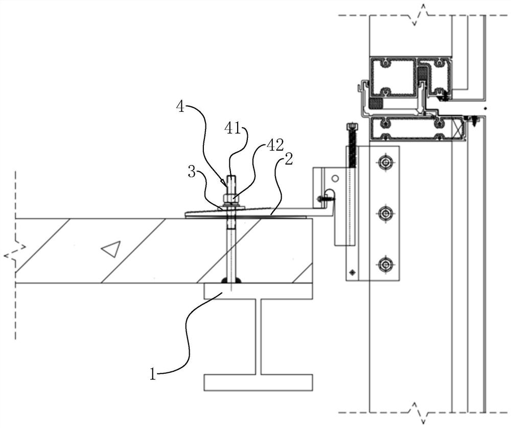
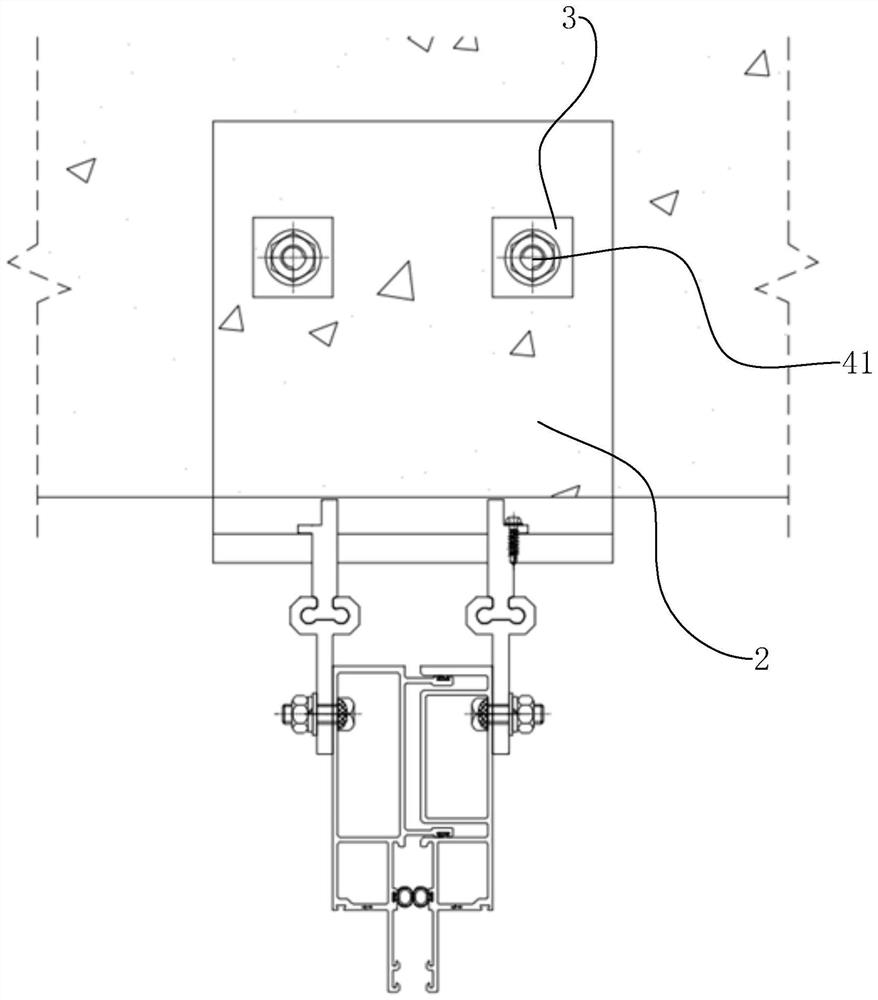
[0041] The embodiment of the present application discloses a connection structure for a unit curtain wall. refer to figure 1 , a connection structure for a unit curtain wall includes an embedded part 1, a platform yard 2, a meson 3 and a connecting part 4. The embedded part 1 is an I-beam, which is used to connect with the connecting part 4, and is realized by the connecting part 4. The embedded part 1 is connected with the platform code 2.
[0042] refer to figure 1 and figure 2 , the connecting piece 4 includes a screw 41 with an external thread and a nut 42 matched with the screw 41. In this embodiment, before pouring concrete, one end of the screw 41 is connected with the embedded piece 1 by welding, and makes The screw 41 is perpendicular to the I-shaped surface of the embedded part 1, and concrete is poured horizontally in the area between the other end of the screw 41 and the embedded part 1. After the concrete is solidified, the other end of the screw 41 is passed th...
Embodiment 2
[0049] The embodiment of the present application discloses a connection structure for a unit curtain wall. refer to figure 1 and figure 2 , the difference between this embodiment and the first embodiment is: the connection method between the screw 41 and the embedded part 1 . Specifically, the embedded part 1 has a connecting hole with an internal thread, and one end of the screw rod 41 is vertically connected to the embedded part 1 through the connecting hole.
[0050] The implementation principle of the second embodiment is as follows: connect one end of the screw 41 with the embedded part 1 threadedly, then pour concrete, pass the upward through hole of the platform 2 with the limiter on the side of the screw 41, and then connect the meson 3 to the screw 41. The platform code 2 is engaged, and then the nut 42 is set on the top of the meson 3 to fix the meson 3, the platform code 2 and the embedded part 1, and the screw 41 is connected with the embedded part 1, which can ...
Embodiment 3
[0052] The embodiment of the present application discloses a connection structure for a unit curtain wall. refer to figure 1 and figure 2 , the difference between this embodiment and the first embodiment is: the connection method between the screw 41 and the embedded part 1 . Specifically, one end of the screw 41 is connected with the embedded part 1 through a sticky piece. In this embodiment, the sticky piece is glue. Apply the glue to one end of the screw 41 and the surface of the embedded piece 1, and then press the screw 41 and the embedded piece 1 to make the glue. stick to each other.
[0053] The implementation principle of the third embodiment is as follows: connect one end of the screw 41 with the embedded part 1 through glue, then pour concrete, pass the upward through hole of the platform code 2 with the limiter on the side of the screw 41, and connect the meson 3 and the The platform yard 2 is engaged, and then the nut 42 is set above the meson 3, and the platf...
PUM
 Abstract
Description
Claims
Application Information
 - R&D Engineer
- R&D Manager
- IP Professional
- Industry Leading Data Capabilities
- Powerful AI technology
- Patent DNA Extraction
Browse by: Latest US Patents, China's latest patents, Technical Efficacy Thesaurus, Application Domain, Technology Topic, Popular Technical Reports.
© 2024 PatSnap. All rights reserved.Legal|Privacy policy|Modern Slavery Act Transparency Statement|Sitemap|About US| Contact US: help@patsnap.com


