Reverse hanging type power roller way system
A roller table system and anti-hanging technology, which is applied in the direction of roller table, mechanical conveyor, transportation and packaging, etc., can solve the problems of no emergency stop mechanism, inability to brake the system in time, and reduce transportation efficiency, so as to reduce safety The probability of hidden dangers, the full use of transmission energy, and the effect of diversification of transmission paths
- Summary
- Abstract
- Description
- Claims
- Application Information
AI Technical Summary
Problems solved by technology
Method used
Image
Examples
Embodiment 1
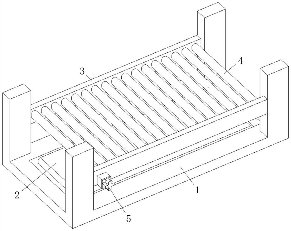
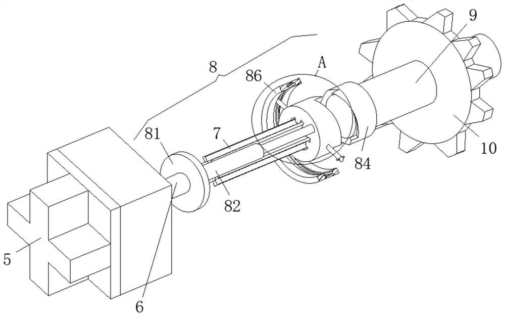
[0023] see Figure 1-2 and Figure 4 , The present invention provides a technical solution: a reverse hanging type power roller table system, comprising a bracket 1, a crawler 2 is installed on the inner bottom surface of the bracket 1, and a horizontal plate 3 is fixed between the side walls of the bracket 1, and the horizontal A roller 4 is rotatably connected between the plates 3, and a motor 5 is installed on the side wall of the horizontal plate 3, the output end of the motor 5 is fixedly connected with a transmission shaft 6, and the outer surface of the transmission shaft 6 is fixedly connected with a clip 7, And an emergency stop mechanism 8 is installed on the outer surface of the transmission shaft 6, and the emergency stop mechanism 8 includes a second clamping column 84. The second clamping column 84 is fixedly sleeved with the rotating shaft 9, and the outer surface of the rotating shaft 9 is fixedly sleeved with the driving gear 10, and the driving gear 10 is fix...
Embodiment 2
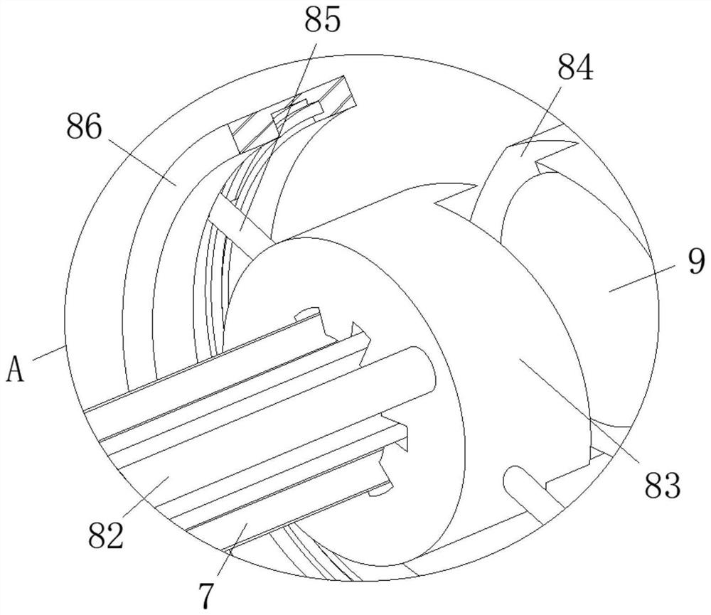
[0026] see Figure 2-5 , the present invention provides a technical solution: a reverse hanging type power roller table system, the emergency stop mechanism 8 includes a fixed plate 81, the fixed plate 81 is fixedly sleeved with the outer surface of the transmission shaft 6, and the end surface of the fixed plate 81 is installed There is an electric push rod 82, the other end of the electric push rod 82 is fixedly connected with a clamping column 1 83, the clamping column 1 83 is fitted and connected with the clamping column 2 84, and a sliding rod 85 is fixed on the outer surface of the clamping column 1 83, and the sliding The other end of the rod 85 is slidably connected with a moving ring 86, the outer surface of the moving ring 86 is fixed with a connecting rod 87, the other end of the connecting rod 87 is fixed with a steel rope 88, and the outer surface of the steel rope 88 is slidably connected with a guide wheel 89 , and the end surface of the steel rope 88 is fixed w...
PUM
 Abstract
Description
Claims
Application Information
 - R&D
- Intellectual Property
- Life Sciences
- Materials
- Tech Scout
- Unparalleled Data Quality
- Higher Quality Content
- 60% Fewer Hallucinations
Browse by: Latest US Patents, China's latest patents, Technical Efficacy Thesaurus, Application Domain, Technology Topic, Popular Technical Reports.
© 2025 PatSnap. All rights reserved.Legal|Privacy policy|Modern Slavery Act Transparency Statement|Sitemap|About US| Contact US: help@patsnap.com


