


Quick Research
Generate reliable direction feasibility study reports for your R&D in just a few steps.

Technical Q&A
Discover and master advanced knowledge NOW. Basics, ideas, possibilities, all at once.

Find Solutions
As an expert in R&D theories, this can generate solutions to your technical problems instantly.

Evaluate Feasibility
Analyze your overall solution with one click, know your potential R&D risks in advance.

Monitor Landscape
Get weekly tech updates, stay abreast of the latest tech innovations and key insights.
Rotating arm guide rail connecting structure
A technology for connecting structures and guide rails, which is applied to building structures, doors, and wing parts, etc., and can solve problems such as unsightly guide rails and damage to the strength of door frames
- Summary
- Abstract
- Description
- Claims
- Application Information
AI Technical Summary
Problems solved by technology
Method used
Image

Examples
Embodiment 1
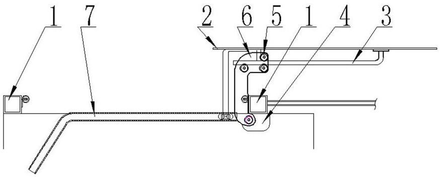
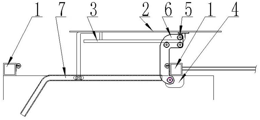
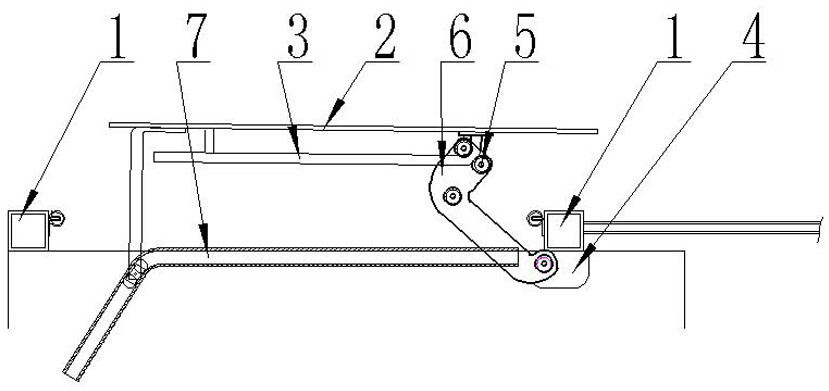
[0018] Example 1: Provide rod-shaped guide rails on the inner surface of the door
[0019] In this example, as Figure 1-4 As shown, the guide rail 3 arranged on the inner surface of the door 2 is rod-shaped, the cross section of the guide rail 3 is circular, that is, a convex arc surface, the straight line section of the guide rail 3 is parallel to the inner surface of the vehicle door 2, and the curved section is connected to the straight line section. Close to one end of the edge door frame, and the curved section is bent toward the door 2, the arm seat 4 is arranged on the inner wall of the body edge door frame corresponding to the horizontal plane of the guide rail 3, the arm 6 is L-shaped, and the long side of the arm 6 is rotatably connected to the arm On the seat 4, it is limited by the side frame of the body door frame 1. There are three rollers 5. The rollers 5 rotate on the roller shaft. The roller 5 is fixed on the short side of the rotating arm through the roller ...
Embodiment 2
[0020] Example 2: Inlay groove-shaped guide rails on the outer peripheral surface of the vehicle body
[0021] The guide rail 3 in this embodiment is in the shape of a groove, and the structure is as follows Figure 5 , Image 6 , set on the side surface of the body on the side of the door opening direction, insert the guide rail 3 on the side surface of the vehicle body along the opening direction of the door 2 at any height of the door 2, and the straight line section of the guide rail 3 is parallel to the length of the vehicle body, and the curved section is close to The body door frame is at the vertical profile skeleton, and the curved section is bent in the horizontal direction of the body, the arm seat 4 is arranged on the door 2 corresponding to the horizontal plane of the guide rail 3, and the long side of the L-shaped arm 6 is rotatably connected to the arm seat 4. Three rollers 5, two guide rollers and one load-bearing roller are arranged at one end of the short si...
Embodiment 3
[0022] Example 3: Arrangement of grooved guide rails on or / and under the body door frame
[0023] The guide rail 3 in this embodiment is in the shape of a groove, and the structure is as follows Figure 5 , Image 6, the guide rail 3 is arranged on the vehicle body above and below the door frame of the vehicle body, the straight line section of the guide rail 3 is parallel to the length of the vehicle body, and the curved section is bent to the horizontal direction in the vehicle body, and the swivel arm seat 4 is arranged on the door corresponding to the horizontal plane of the guide rail, and the rotation The arm 6 can be L-shaped or T-shaped. The long side of the rotating arm 6 is rotatably connected to the rotating arm seat, and one end of the short side of the rotating arm 6 is provided with three rollers, two guide rollers and a load-bearing roller, and two guide rollers. The roller shaft is connected to the short side of the L-shaped or T-shaped turning arm 6 at 90 deg...
PUM
 Abstract
Description
Claims
Application Information
 - R&D Engineer
- R&D Manager
- IP Professional
- Industry Leading Data Capabilities
- Powerful AI technology
- Patent DNA Extraction
Browse by: Latest US Patents, China's latest patents, Technical Efficacy Thesaurus, Application Domain, Technology Topic, Popular Technical Reports.
© 2024 PatSnap. All rights reserved.Legal|Privacy policy|Modern Slavery Act Transparency Statement|Sitemap|About US| Contact US: help@patsnap.com