Telescopic device of building highway bridge guardrail

A technology for highway bridges and telescopic devices, which is applied in construction, bridges, bridge construction, etc., can solve the problems of troublesome use, inconvenient operation and use, time-consuming and laborious, etc., and achieves convenient use, enhanced support stability, and convenient and time-saving use. Effect

Inactive Publication Date: 2022-07-15
郭兴方
View PDF0 Cites 0 Cited by
  • Summary
  • Abstract
  • Description
  • Claims
  • Application Information

AI Technical Summary

Problems solved by technology

[0003] Most of the crossbars on the telescopic movable components of existing telescopic devices can slide in order to cooperate with the overall telescopic function, but the optimized design of the driving and sliding structure is not reasonable enough, and the overall lifting and sliding force of the telescopic movable components cannot be used to drive the sliding Lifting, resulting in the need for additional manual operation of the lifting and lowering rails when the telescopic guardrail body is used, the operation is more troublesome and inconvenient. In addition, in order to ensure the stability of the stretched state, most telescopic devices are equipped with at least two sets of positioning components at the top and bottom. Most of the two sets of positioning components It cannot be linked and combined with synchronous drive, so when the body of the telescopic guardrail needs to be inserted and tightened step by step, the two sets of positioning components need to be inserted and tightened step by step, which is troublesome to use, time-consuming and labor-intensive

Method used


Image

  • Telescopic device of building highway bridge guardrail
  • Telescopic device of building highway bridge guardrail
  • Telescopic device of building highway bridge guardrail

Examples


Embodiment Construction

[0025] The technical solutions in the embodiments of the present invention will be clearly and completely described below with reference to the accompanying drawings in the embodiments of the present invention. Obviously, the described embodiments are only a part of the embodiments of the present invention, but not all of the embodiments.

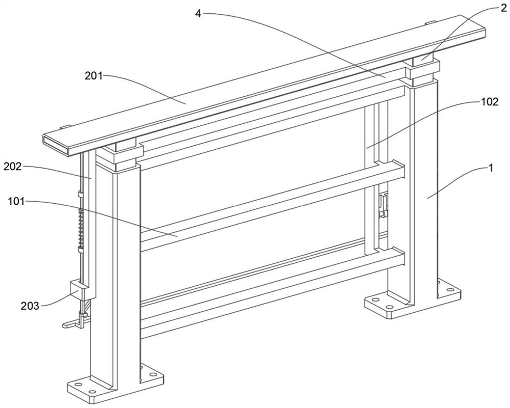
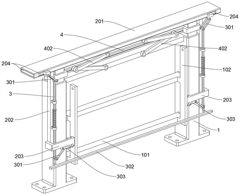
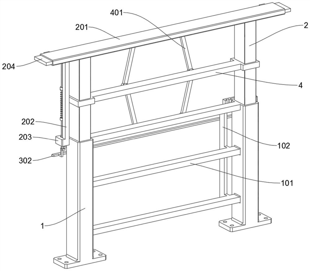
[0026] see Figure 1 to Figure 10 ;

[0027] The present invention proposes a telescopic device for building a highway bridge guardrail, comprising: a ground contact support portion 1; the ground contact support portion 1 includes a transverse support connection pipe 101, and the ground contact support portion 1 is integrally supported by two vertical support square pipes on the left and right. and three horizontal bracing connection pipes 101 welded between two vertical bracing square pipes at equal distances up and down. The bottom of the head end of the plate 203 is welded with two lifting rings at intervals, the two positioning rods 30...


PUM


Abstract

The invention discloses a telescopic device of a building highway bridge guardrail, and relates to the technical field of highway bridge guardrails. The whole ground contact supporting part is jointly composed of a left vertical supporting square pipe, a right vertical supporting square pipe and three transverse supporting connecting pipes which are welded between the two vertical supporting square pipes at equal intervals up and down, and a sliding supporting part is slidably inserted into the two vertical supporting square pipes; the sliding supporting part comprises a top supporting holding pipe and a vertical supporting hanging rod, the whole sliding supporting part is jointly composed of a left vertical sliding pipe, a right vertical sliding pipe and the top supporting holding pipe transversely welded to the top ends of the two vertical sliding pipes, and a sliding handrail is installed on the two vertical sliding pipes in a sliding mode. Through the four-connecting-rod sliding telescopic mechanism, when the sliding supporting part is lifted upwards, the sliding handrail can be driven to slide upwards to be positioned in the middle of the sliding supporting part in a linkage mode to implement impact interception, and the trouble that the sliding handrail is additionally lifted and positioned when the sliding supporting part is stretched is solved.

Description

technical field [0001] The invention relates to the technical field of highway bridge guardrails, in particular to a telescopic device for building highway bridge guardrails. Background technique [0002] When transporting objects with larger widths on some narrow highway bridges, they will be blocked by the left and right guardrails, so it is necessary to set up telescopic devices for the guardrails of highway bridges. [0003] Most of the cross bars on the telescopic movable assembly of the existing telescopic device can slide in order to cooperate with the overall telescopic function, but the optimal design of the driving sliding structure is not reasonable enough, and the overall lifting and sliding force of the telescopic movable assembly cannot be used to drive the sliding. As a result, when the guardrail body is retracted, it is necessary to manually operate the lifting and lowering bar, which is more troublesome and inconvenient to operate. In addition, in order to e...

Claims


Application Information

Patent Timeline
Patent Type & Authority Applications(China)
IPC IPC(8): E01D19/10
CPCE01D19/103
Inventor 郭兴方
Owner 郭兴方
Why Eureka
Try Eureka