
Method for calculating fatigue life of belt type CVT steel belt ring under high rotating speed condition

A fatigue life and calculation method technology, applied in the field of metal belt CVT technology research, can solve the problems of easy fracture of steel belt rings, reduced reliability, and a large number of loads.

Pending Publication Date: 2022-07-08
XIANGTAN UNIV
View PDF0 Cites 2 Cited by
  • Summary
  • Abstract
  • Description
  • Claims
  • Application Information

AI Technical Summary

Problems solved by technology

[0003] However, experiments have shown that the reliability of CVT will be greatly reduced under high speed conditions, and the outermost steel belt ring of the metal steel belt is very easy to break, resulting in CVT failure. The failure time is much earlier than normal damage, and it is very likely that the belt ring due to fatigue failure
However, due to the specific experimental conditions and the special structure of the CVT, it is impossible to obtain the actual load on the belt ring at high speed through the experiment, and the entire ring of the CVT steel belt ring is subjected to load, and the number of loads at the same time numerous
Due to the continuous rotation of the belt ring, the position of the load application point is also constantly changing, which makes it difficult to calculate the fatigue life of the belt ring

Method used


Image

  • Method for calculating fatigue life of belt type CVT steel belt ring under high rotating speed condition
  • Method for calculating fatigue life of belt type CVT steel belt ring under high rotating speed condition
  • Method for calculating fatigue life of belt type CVT steel belt ring under high rotating speed condition

Examples


Embodiment Construction

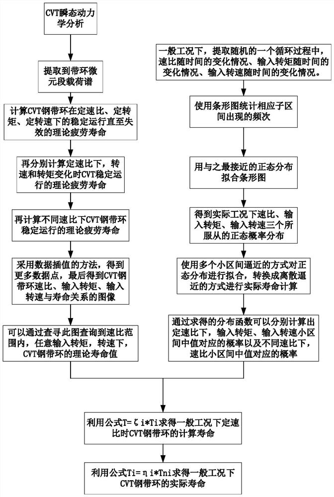
[0053] The present invention will be described in further detail below in conjunction with the accompanying drawings. The present invention adopts a calculation scheme such as figure 1 shown, the specific steps are as follows:

[0054] Step 1: Do the transient dynamic analysis of the belt CVT;

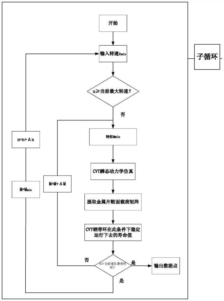
[0055] Step 2: Use the equivalent method to extract the load spectrum of the micro-element section of the steel belt ring for one week, and then calculate the fatigue life of the steel belt ring under the specified conditions;

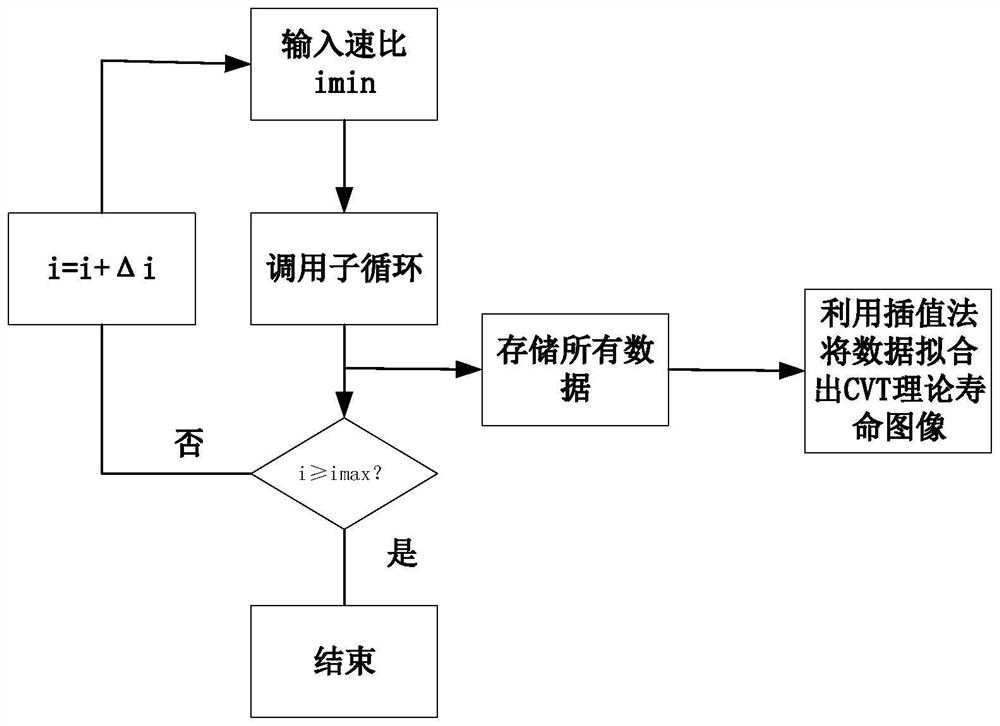
[0056] Step 3: Considering the two situations of speed, torque change and speed ratio change under a fixed speed ratio, use the same life calculation method as in the previous step and combine the data interpolation method to obtain the theoretical life image of the CVT belt ring;

[0057] Step 4: Consider the general working conditions, first use statistical methods to obtain the probability distribution of the general working condition speed ratio, input tor...


PUM


Abstract

The invention relates to a method for calculating the fatigue life of a belt type CVT steel belt ring under a high rotating speed condition. The method comprises the following steps: carrying out belt type CVT transient dynamic analysis; obtaining a load spectrum of the infinitesimal section of the steel belt ring running for one circle by using an equivalent method, and then calculating the fatigue life of the belt ring under the specified condition; respectively considering two types of conditions of rotating speed, torque change and speed ratio change under a fixed speed ratio, and obtaining a theoretical life image of the CVT belt ring by using a life calculation method which is the same as the previous two steps and combining a data interpolation method; the method comprises the following steps: firstly, obtaining probability distribution obeyed by a general working condition speed ratio, an input torque and an input rotating speed by using a statistical method; calculating the life of a belt ring at a constant speed ratio by considering the probability of a CVT theoretical life image and an input condition; and finally, obtaining the actual service life of the belt ring under general working conditions by using the service life of the belt ring with different speed ratios and the probability distribution obeyed by the speed ratios. The method for calculating the fatigue life of the steel belt ring is provided from the theoretical angle, and the fatigue life of the steel belt ring can be accurately estimated.

Description

technical field [0001] The invention relates to the technical research field of a metal belt type CVT under the condition of high rotational speed, in particular to a method for calculating the fatigue life of a metal steel belt ring under the condition of high rotational speed. Background technique [0002] With the continuous development of society, automobiles have become an indispensable means of transportation for people to travel, but with it comes the thorny problem of increasingly serious environmental pollution caused by a large number of automobile exhausts. All countries in the world attach great importance to environmental issues. Electric vehicles use batteries as a power source and are an emission-free means of transportation. As the country continues to strictly control the parameters of vehicle emission indicators, electric vehicles are expected to replace traditional vehicles and become the main means of travel for people in the future. Studies have shown t...

Claims


Application Information

Patent Timeline
IPC IPC(8): G06F30/17G06F30/15G06F30/20G06F119/02G06F119/14
CPCG06F30/17G06F30/15G06F30/20G06F2119/02G06F2119/14Y02T90/00
Inventor 刘金刚陈实林马凯彭晓宇傅兵郑剑云
Owner XIANGTAN UNIV
Learn More