Assembling and stacking structure
A technology of stacking structure and limiting structure, applied in the directions of packaging, transportation and packaging, rigid containers, etc., can solve the problems of simple appearance, exposure, and large locking structure size, and achieve simple appearance, easy portability, and improved use convenience. sexual effect
- Summary
- Abstract
- Description
- Claims
- Application Information
AI Technical Summary
Problems solved by technology
Method used
Image

Examples
Embodiment 1
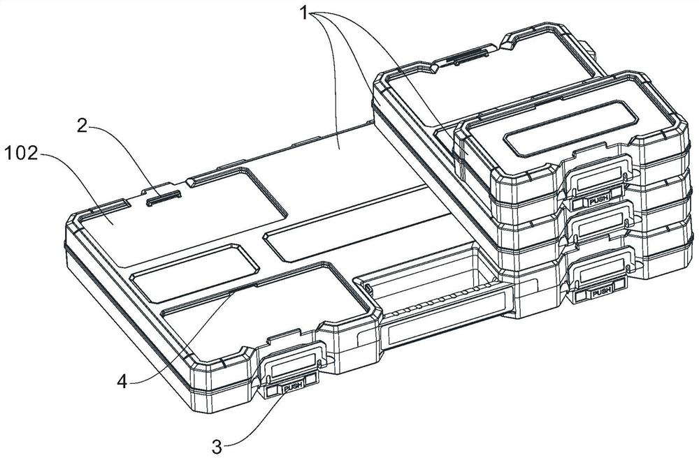
[0037] like Figure 1 to Figure 7 As shown, an assembled stacking structure includes three stackable containers 1, the three containers are respectively large, medium and small, with three different sizes, the length of the medium container is equal to the width of the large container, The length of the small container is equal to the width of the medium container. The container 1 is a blow tool box with a box body and a flip cover. Each container 1 is provided with a first engaging portion 2 and a locking member 3. The first engaging portion 2 is located at the top of the container 1, that is, the top of the flip cover, and the locking member 3 is located at the bottom of the container 1, that is, the bottom of the box. Every two adjacent containers of the three stacked containers 1 are connected by a locking structure and an auxiliary limiting structure, and the locking structure and the auxiliary limiting structure are located at the opposite ends of the joint surfaces of ...
Embodiment 2
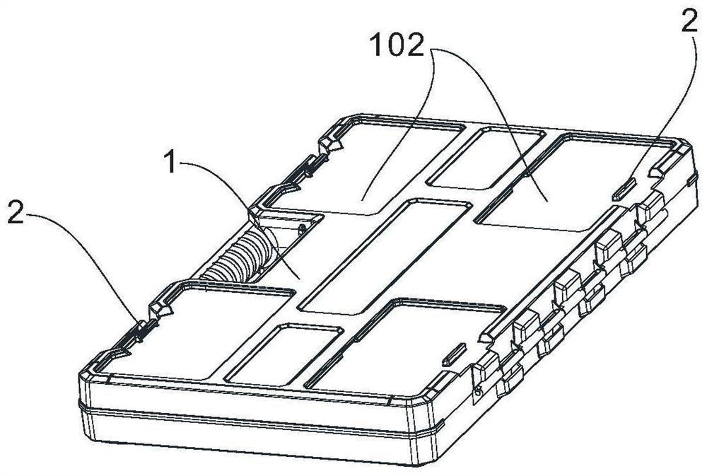
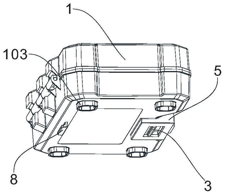
[0040] like Figure 8a , Figure 8b As shown, there are two containers 1, both of which are large containers. The top of the container 1 is provided with a groove 102 , and each of the four corners of the bottom of the container 1 is provided with a foot 103 , and the foot 103 is integrally formed with the box body of the container 1 . When the containers 1 are stacked on each other, the feet 103 of the upper container 1 are located in the grooves 102 of the lower container 1 and each of the feet 103 abuts against a groove wall of a corresponding groove 102 . The groove 102 is rectangular, one groove 102 is set on the top of the small container, two grooves 102 are set on the top of the medium container, and four grooves 102 are set on the top of the large container. Each groove 102 is provided with a first engaging portion 2 therein. The rest are the same as in Example 1.
[0041] When the two containers 1 are stacked and matched, under the action of the locking structure...
Embodiment 3
[0043] like Figure 9a , Figure 9b As shown, the width of the locking member 3 is smaller than the width of the locking member slot 5, one end of the spring 6 abuts on the right side wall of the locking member slot 5, and the other end of the spring 6 abuts on the right side wall of the bottom frame 301 superior. The length of the slot inside the first engaging portion 2 is only half the length of the first engaging portion 2 and is offset from the left half of the first engaging portion 2 . The locking member 3 slides in a direction perpendicular to the axial direction of the locking member slot 5 , and the sliding direction of the locking member 3 is parallel to the first engaging portion 2 . In the unlocked state, the locking member engaging portion 303 and the first engaging portion 2 dislocation separation. The rest are the same as in Example 2.
[0044] When the two containers 1 are stacked and matched, the first engaging portion 2 of the lower container 1 extends i...
PUM
 Abstract
Description
Claims
Application Information
 - R&D
- Intellectual Property
- Life Sciences
- Materials
- Tech Scout
- Unparalleled Data Quality
- Higher Quality Content
- 60% Fewer Hallucinations
Browse by: Latest US Patents, China's latest patents, Technical Efficacy Thesaurus, Application Domain, Technology Topic, Popular Technical Reports.
© 2025 PatSnap. All rights reserved.Legal|Privacy policy|Modern Slavery Act Transparency Statement|Sitemap|About US| Contact US: help@patsnap.com