Wall switch

A technology for wall switches and switch holders, which is applied in the direction of electric switches, parts of flip switches/rocker switches, electrical components, etc., and can solve the problems of reducing the use effect of the overall structure, irregularity, and easy falling off of wall switches

Pending Publication Date: 2022-07-05
WENZHOU GUANGTAI ELECTRICAL APPLIANCE
View PDF0 Cites 0 Cited by
  • Summary
  • Abstract
  • Description
  • Claims
  • Application Information

AI Technical Summary

Problems solved by technology

[0002] The wall switch refers to the electrical switch installed on the wall, which is used to connect and disconnect the circuit and control the switch of the light. The wall switch has various forms of single open, double open or multiple open, in order to meet the needs of use During installation, multiple wall switches are usually installed side by side to meet the control of multiple lighting lamps, making the whole more compact and beautiful, but at present, during construction, it is easy to appear that the installation wall is uneven, or the wall bottom box Errors are prone to occur after pre-embedding, resulting in irregular problems. However, the existing wall switches have uniform specifications, which makes the overall structure not well installed, especially when multiple switches are installed side by side. These processing errors are fatal, making the wall After the switch is installed, it is easy to fall off, which is not conducive to improving the use effect of the overall structure, cannot well adapt to the use needs, and reduces the use effect of the overall structure, and the existing structure lacks a switch status display unit, which is not convenient for turning on the lights at night

Method used


Image

  • Wall switch
  • Wall switch
  • Wall switch

Examples


Embodiment Construction

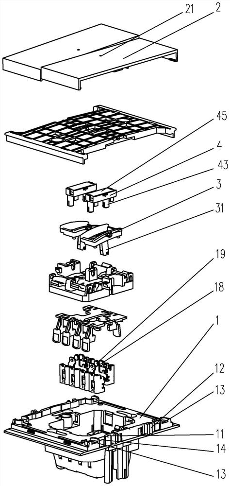
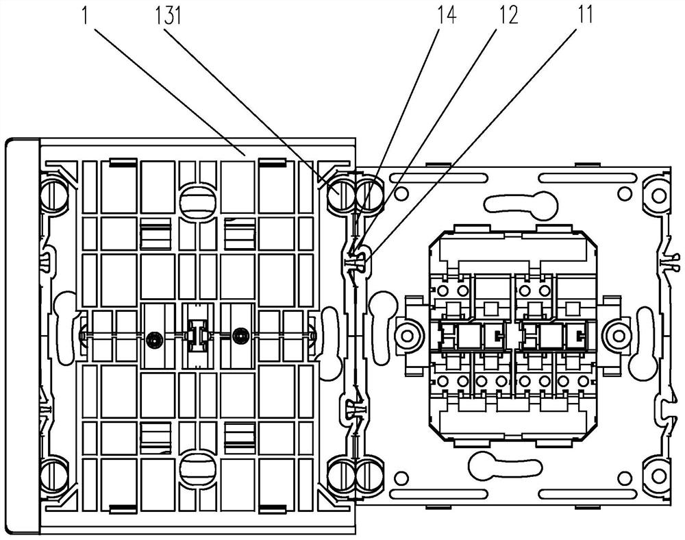
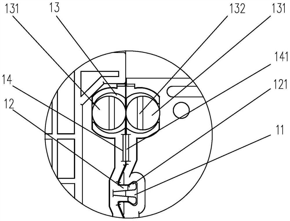
[0032] An embodiment of a wall switch of the present invention is as follows figure 1 and Figure 8 Shown: it includes a switch base 1 and a dial button 2, the dial button 2 is rotatably arranged on the switch base 1, the switch base 1 is oscillated and provided with a swing base 3, and the swing base 3 is connected to the dial button 2 by transmission, The switch base 1 is also provided with a lamp holder 4, the lamp holder 4 is provided with a light-emitting unit 42, and the swing base 3 is also provided with a touch switch for changing the state of the light-emitting unit 42 when the toggle 2 is opened and closed. The head 31, the dial button 2 is provided with a display slot 21 corresponding to the position of the lamp holder 4, the side of the switch base 1 is provided with a connecting slot 11 and a connecting piece, and the connecting slot 11 is clamped with the connecting piece of the adjacent switch base 1 The switch seat 1 is formed to be connected side by side with...


PUM


Abstract

A wall switch disclosed by the present invention comprises a switch base and a toggle, the toggle is rotatably arranged on the switch base, a swing base is arranged on the switch base in a swing manner, the swing base is in transmission connection with the toggle, the switch base is also provided with a lamp holder, a light-emitting unit is arranged in the lamp holder, and the light-emitting unit is arranged on the switch base. The swing seat is further provided with a contact used for changing the state of the light-emitting unit when the toggle switch is switched on and switched off, a display groove is formed in the position, corresponding to the lamp holder, of the toggle switch, a connecting groove and a connecting piece are arranged on the side edge of the switch seat, and the connecting groove is clamped with the connecting piece of the adjacent switch seat to be connected with the adjacent switch seat side by side. The switch base is provided with a mounting groove in the side direction of the connecting groove and the connecting piece, and an eccentric wheel is rotationally arranged in the mounting groove. The structure is simple, the installation time interval is convenient to adjust, connection is stable, and meanwhile the prompt identification function is achieved.

Description

technical field [0001] The present invention relates to a wall switch. Background technique [0002] The wall switch refers to the electrical switch installed on the wall, which is used to connect and disconnect the circuit, and control the switch of the lighting lamp. The wall switch has various forms of single opening, double opening or multiple opening. , During installation, multiple wall switches are usually installed in parallel to meet the control of multiple lights, making the whole more compact and beautiful, but at present, during construction, it is easy to install uneven walls, or wall bottom boxes Errors are prone to occur after pre-embedding, resulting in irregularities, and the existing wall switches have uniform specifications, so that the overall structure cannot be installed well, especially when multiple switches are installed side by side, these processing errors are fatal, making the wall After the switch is installed, it is easy to fall off, which is n...

Claims


Application Information

Patent Timeline
IPC IPC(8): H01H23/04H01H23/08H01H23/02H01H23/14H01H9/16
CPCH01H23/04H01H23/08H01H23/025H01H23/14
Inventor 朱克淼龚开亮
Owner WENZHOU GUANGTAI ELECTRICAL APPLIANCE
Why Eureka
Try Eureka