
Display driving method and system and display terminal

A technology for display driving and displaying data, which is applied to static indicators, instruments, etc., can solve the problems of large instantaneous voltage difference of display data polarity change, uneven voltage value of display data, polarization of liquid crystal molecules, etc., to avoid voltage disturbance , to avoid the bad effect of afterimage

Active Publication Date: 2022-07-01
BEIJING ESWIN COMPUTING TECH CO LTD
View PDF7 Cites 0 Cited by
  • Summary
  • Abstract
  • Description
  • Claims
  • Application Information

AI Technical Summary

Problems solved by technology

However, when the positive and negative frame transitions, the polarity change of the display data provided by the source drive circuit to the pixel unit will generate a large instantaneous voltage difference, and then it is easy to disturb the common voltage received in the pixel unit during display, which will cause positive and negative frame The voltage value of the displayed data is uneven during display, and the voltage asymmetry for a long time will further lead to the polarization of the liquid crystal molecules, and finally the afterimage phenomenon will appear

Method used


Image

  • Display driving method and system and display terminal
  • Display driving method and system and display terminal
  • Display driving method and system and display terminal

Examples


Embodiment Construction

[0036] In order to facilitate understanding of the present application, the present application will be described more fully below with reference to the related drawings. The preferred embodiments of the present application are shown in the accompanying drawings. However, the present application may be implemented in different forms and is not limited to the embodiments described herein. Rather, these embodiments are provided so that a thorough and complete understanding of the disclosure of this application is provided.

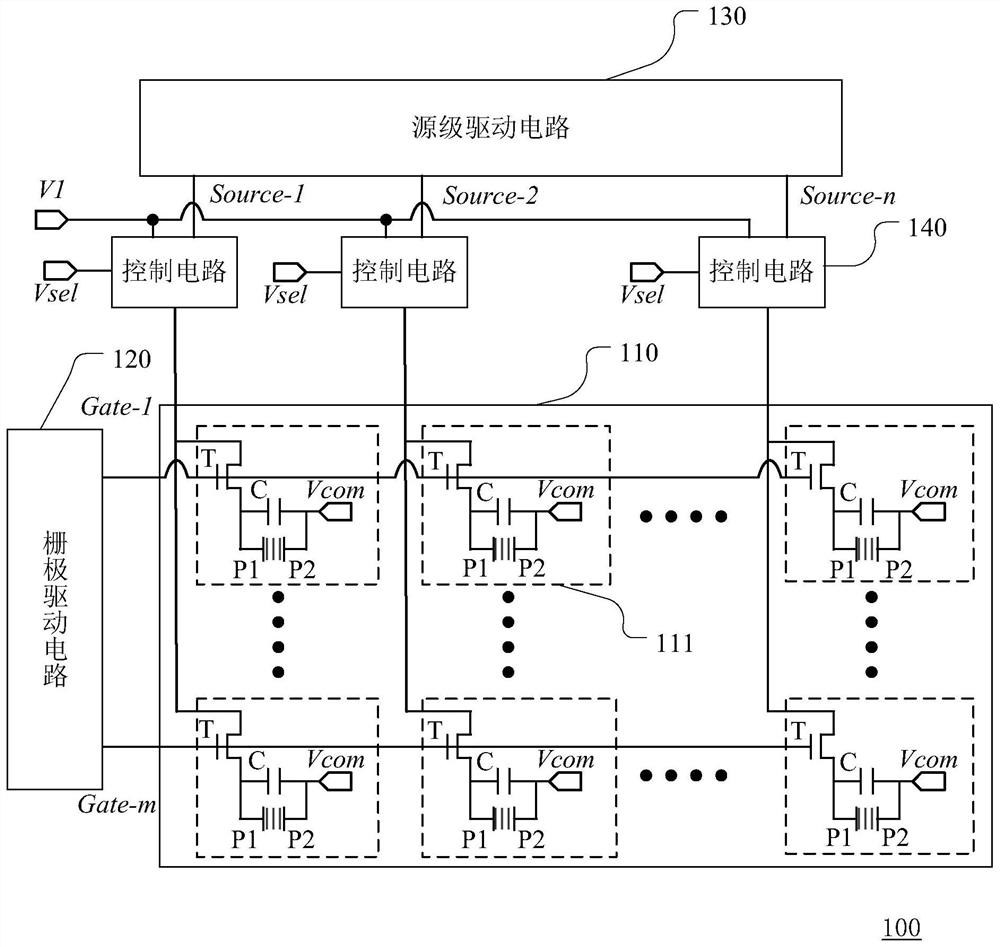
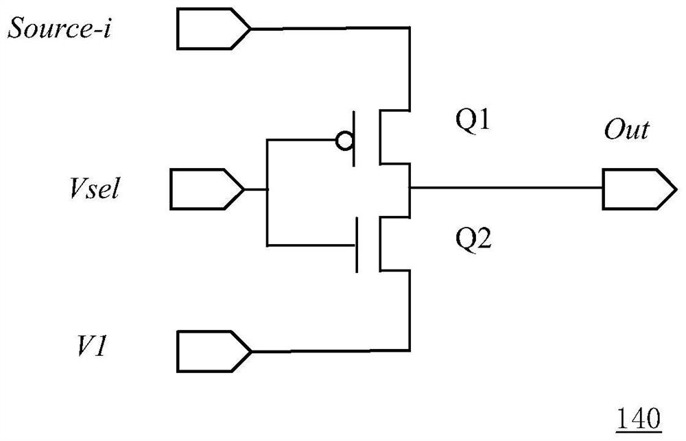
[0037] figure 1 A schematic structural diagram of the display driving system provided according to the first embodiment of the present application is shown. figure 2 A schematic structural diagram of a control circuit in a display driving system provided according to the first embodiment of the present application is shown.

[0038] see figure 1 , the display driving system 100 includes a panel 110 , a gate driving circuit 120 , a source driving circuit...


PUM


Abstract

The invention discloses a display driving method and system and a display terminal, and the display driving system comprises a panel which comprises a plurality of pixel units arranged in an array; the gate driving circuit is used for controlling the on or off of each row of pixel units; the source electrode driving circuit comprises a plurality of source electrode driving units, one source electrode driving unit is used for providing display data for the pixel units located in the same column, and the polarities of the display data provided for the same pixel unit are opposite when adjacent frames are displayed; and the control circuit is connected between the source electrode driving unit and the pixel units, and is used for writing an intermediate voltage into the pixel electrodes of the plurality of pixel units in the corresponding row for pre-charging when one row of pixel units is conducted, and then writing display data into the pixel electrodes of the plurality of pixel units in the corresponding row. The data voltage is provided for the pixel units step by step, so that overhigh instantaneous voltage change is avoided, voltage disturbance to other signals is further avoided, and finally bad residual images are avoided.

Description

technical field [0001] The present application relates to the field of display technology, and in particular, to a display driving method, system and display terminal. Background technique [0002] With the popularization of electronic products, display devices are becoming more and more diversified. Liquid Crystal Display (LCD) has many advantages such as lightness, thinness, energy saving, etc., and is widely used in high-definition electronic equipment. [0003] The panel in the liquid crystal display device includes a pixel array, the pixel array includes a plurality of pixel units, each pixel unit has a first substrate, a second substrate opposite to each other, and liquid crystal molecules located therebetween, the first substrate and the second An electric field is generated between the common electrode on the substrate and the pixel electrode, and the electric field controls the rotation of the liquid crystal molecules, thereby changing the light transmittance of ea...

Claims


Application Information

Patent Timeline
Patent Type & Authority Applications(China)
IPC IPC(8): G09G3/36
CPCG09G3/3696G09G2310/0251G09G2310/0264G09G2320/0257
Inventor 胡巍浩倪恩伟南帐镇赵楠李阳恒陈伟雄
Owner BEIJING ESWIN COMPUTING TECH CO LTD
Learn More