
Patsnap Eureka
For R&D, Patsnap Eureka makes reading and utilizing patents & technical documents easy.
Patsnap Eureka AIR
Designed for self-driven R&D workflows. Generate viable solutions, solve complex R&D challenges, empower your innovation with AI.

Patsnap Eureka Materials
Designed for material experts only. Revolutionize your material R&D, from search, analyze, to developing new materials.

TechResearch
Generate reliable direction feasibility study reports for your R&D in just a few steps.

TechSeek
Discover and master advanced knowledge NOW. Basics, ideas, possibilities, all at once.

TechMind
As an expert in R&D Theories, TechMind can generates customized viable solutions instantly.

TechRisk
Analyze your overall solution with one click, know your potential R&D risks in advance.

TechMonitor
Get weekly tech updates, stay abreast of the latest tech innovations and key insights.
Non-contact proximity switch and valve position indicating system
A proximity switch, non-contact technology, applied in electrical switches, magnetic field/electric field switches, electrical connection of contacts, etc., can solve problems such as false signals and malfunction of proximity switches
- Summary
- Abstract
- Description
- Claims
- Application Information
AI Technical Summary
Problems solved by technology
Method used
Image

Examples
Embodiment 1
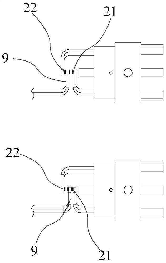
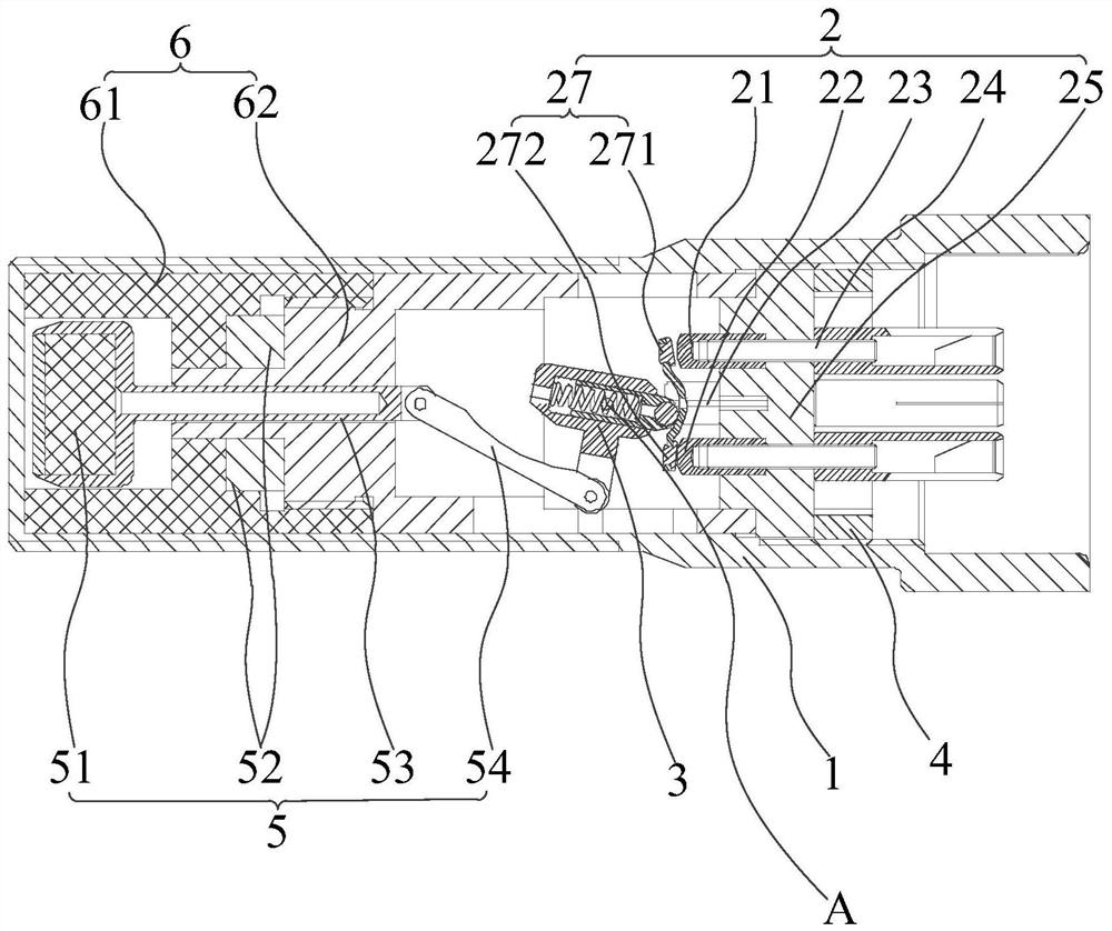
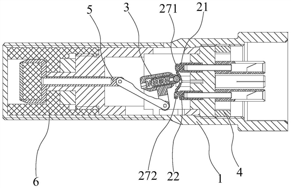
[0066] figure 2 A schematic structural diagram of the non-contact proximity switch provided in this embodiment in a working state, image 3 for figure 2 The schematic diagram of the structure of the non-contact proximity switch shown in the non-working state. Here, it is defined that the first movable contact 271 is in a non-working state when it is in contact with the first stationary contact 21 , and it is an operating state when the second movable contact 272 is in contact with the second stationary contact 22 . like Figure 2-3 As shown, the non-contact proximity switch provided in this embodiment includes a housing 1 , a contact base 2 , an elastic component 3 , and a driving component 5 . The housing 1 includes an open end and a closed end, and serves as a housing for the proximity switch. In this embodiment, the diameter and length of the housing 1 are not limited, and those skilled in the art can set them according to actual needs.
[0067] A possible implementa...
Embodiment 2
[0093] Figure 7 This is a partial structural schematic diagram of the valve position indication system provided in this embodiment. On the basis of the first embodiment, this embodiment also provides a valve position indication system, including a valve, a bracket, an electrical connector 8, an indicator, and the non-contact proximity switch in the first embodiment.
[0094] The valve stem of the valve is provided with a target 7 , and this embodiment does not limit the fixing method of the target 7 and the valve stem, and those skilled in the art can set it according to actual needs. Both the valve and the proximity switch are installed on the bracket, and the subsequent circuit is electrically connected to the contacts of the proximity switch through the electrical connector 8, wherein the indicator is located on the subsequent circuit, that is, the circuit electrically connected to the proximity switch.
[0095] like Figure 5 and Figure 7 As shown, the electrical conn...
PUM
 Abstract
Description
Claims
Application Information
 - R&D Engineer
- R&D Manager
- IP Professional
- Industry Leading Data Capabilities
- Powerful AI technology
- Patent DNA Extraction
Browse by: Latest US Patents, China's latest patents, Technical Efficacy Thesaurus, Application Domain, Technology Topic, Popular Technical Reports.
© 2024 PatSnap. All rights reserved.Legal|Privacy policy|Modern Slavery Act Transparency Statement|Sitemap|About US| Contact US: help@patsnap.com