Non-contact proximity switch and valve position indicating system

A non-contact, proximity switch technology, applied in the direction of electric switches, contacts, electrical components, etc., can solve the problems of proximity switch misoperation, false signal, etc., to avoid contact misoperation, enhance anti-vibration performance, and improve stability sexual effect

Pending Publication Date: 2022-01-18
江苏利核仪控技术有限公司 +1
View PDF0 Cites 0 Cited by
  • Summary
  • Abstract
  • Description
  • Claims
  • Application Information

AI Technical Summary

Problems solved by technology

[0004] When there is vibration in the working environment, for example, when the proximity switch is installed in a high-vibration environment such as a pipeline, the vibration of the magnetic part will cause the proximity switch to malfunction and generate false signals

Method used


Image

  • Non-contact proximity switch and valve position indicating system
  • Non-contact proximity switch and valve position indicating system
  • Non-contact proximity switch and valve position indicating system

Examples


Embodiment Construction

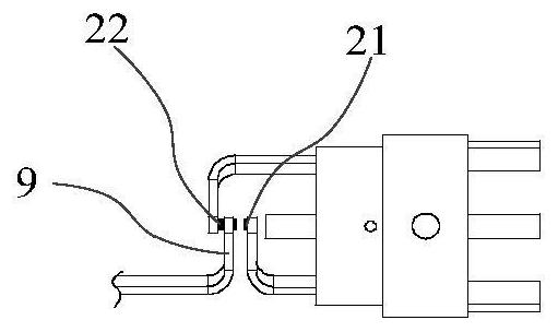
[0033] figure 1 It is a structural schematic diagram of the open state of the proximity switch of the related technology; figure 2 It is a structural schematic diagram of a closed state of a proximity switch in the related art. Such as figure 1 and figure 2 As shown, the existing proximity switch includes a housing, a first stationary contact 21 and a second stationary contact 22 fixedly arranged on the housing, and a movable contact arm 9 . The movable contact arm 9 is located between the first stationary contact 21 and the second stationary contact 22 . Two movable contacts are respectively arranged on the left and right sides of the free end of the movable contact arm 9 . The movable contact arm 9 contacts the first static contact 21 when it moves to the right end, and contacts the second static contact 22 when it moves to the left end. However, when the movable contact arm 9 of the proximity switch vibrates in a vibrating environment, resulting in non-stop switching...


PUM


Abstract

The invention provides a non-contact proximity switch and a valve position indicating system, and relates to the technical field of switch control. The proximity switch is used for solving the problems that when vibration exists in the working environment of an existing proximity switch, vibration of a magnetic piece can cause misoperation of the proximity switch, and false signals are generated. The non-contact proximity switch comprises a first static contact and a second static contact which are oppositely arranged at an interval, and a first movable contact and a second movable contact are arranged on the first side of the rotating part at an interval; and a limiting block is arranged between the first static contact and the second static contact in the opposite direction of the first static contact and the second static contact, and the driving device drives the elastic assembly to rotate so as to drive the rotating piece to rotate around the limiting block, so that the first movable contact is in contact with the first static contact, or the second movable contact is in contact with the second static contact. The driving device drives the elastic assembly to rotate so as to drive the rotating piece to rotate around the limiting block, linear motion of the non-contact proximity switch is changed into rotary motion, and the anti-vibration performance of the non-contact proximity switch is enhanced.

Description

technical field [0001] The invention relates to the technical field of switch control, in particular to a non-contact proximity switch and a valve position indicating system. Background technique [0002] The non-contact proximity switch is a position switch that can output switch signals without contacting external components. When the distance between the target and the sensing surface of the switch is less than or greater than the action threshold, the proximity switch changes state and outputs a switch signal. [0003] Most of the existing non-contact proximity switches use magnetic parts to directly drive the switch contacts, and the magnetic parts and contacts are rigidly connected. [0004] When there is vibration in the working environment, for example, when the proximity switch is installed in a high-vibration environment such as a pipeline, the vibration of the magnetic part will cause the proximity switch to malfunction and generate false signals. Contents of th...

Claims


Application Information

Patent Timeline
IPC IPC(8): H01H1/50
CPCH01H1/50
Inventor 唐秋华陈峰刘桂兴王旭陶宇杰张冬明张恒镭姚旭栋马旭升陈毅斌
Owner 江苏利核仪控技术有限公司
Why Eureka
Try Eureka