
Integrated rainproof box structure of large transformer

A transformer and integrated technology, applied in the field of transformers, can solve the problems of rainwater infiltration into the meter and the influence of the normal use of the meter, and achieve the effect of reducing the occupied space and improving the convenience

Pending Publication Date: 2022-06-24
BAODING TIANWEI BAOBIAN ELECTRICAL
View PDF0 Cites 0 Cited by
  • Summary
  • Abstract
  • Description
  • Claims
  • Application Information

AI Technical Summary

Problems solved by technology

[0004] In order to make up for the deficiencies of the existing technology and solve the problem that the meter is exposed in the air, and rainwater will seep into the meter in rainy days, which will affect the normal use of the meter in the long run, the present invention proposes a large-scale transformer integrated Type rainproof box structure

Method used


Image

  • Integrated rainproof box structure of large transformer
  • Integrated rainproof box structure of large transformer
  • Integrated rainproof box structure of large transformer

Examples


Embodiment 1

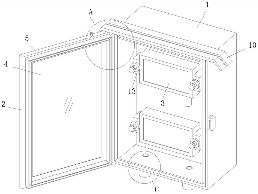
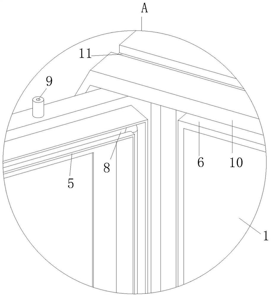
[0027] see Figure 1-6 As shown, a large-scale transformer integrated rainproof box structure includes a structural box 1 and a sealed door 2 hinged on the surface of the structural box 1. A meter 3 is installed inside the structural box 1, and the sealed door 2 A glass observation window 4 is fixed on the surface, the meter 3 and the structural box 1 are connected by a cross-mounting plate 12, and the bottom of the structural box 1 is provided with a threading hole 21; The meter 3 is installed inside the structural box 1, and then the sealing door 2 is closed and locked, which can realize the rainproof function, prevent rainwater from infiltrating into the interior of the meter 3, and at the same time prevent the meter 3 from being scattered and difficult to carry out rainproof treatment, and The meter 3 can be centrally managed to reduce the occupied space, and at the same time, the scale of the meter 3 can be observed through the glass observation window 4 .

[0028] A sea...

Embodiment 2

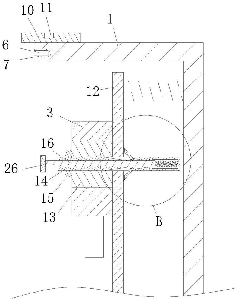
[0036] see Figure 7 As shown, Comparative Example 1, as another embodiment of the present invention, wherein the end of the locking rod 16 is provided with a limit ring 26, the limit ring 26 and the locking rod 16 are connected by a threaded sleeve , when the meter 3 is disassembled, the locking ring 15 needs to be rotated to separate it from the fixing rod 14, and the locking ring 15 can be limited by the limiting ring 26 to prevent the locking ring 15 from being removed from the fixing rod 14. To avoid the loss caused by random throwing and dropping, and prevent the impact on the reuse.

[0037] Working principle, when rainproofing the meter 3, multiple sets of meters 3 need to be installed inside the structural box 1. During installation, the meter 3 is corresponding to the transitional mounting plate 12, and then the locking rod is pressed by pressing the locking rod. 16. Fold the locking buckle 17 inward, and then pass the fixing rod 14 through the fixing block 13 and t...


PUM


Abstract

The invention belongs to the field of transformers, and particularly relates to a large transformer integrated rainproof box structure which comprises a structure box body and a sealing door hinged to the surface of the structure box body, a meter is installed in the structure box body, and a glass observation window is fixed to the surface of the sealing door. The meter is connected with the structural box body through a transition mounting plate, and a threading hole is formed in the bottom of the structural box body; the multiple sets of meters are installed in the structural box body through the transition installation plate, so that the sealing strip is extruded, the sealing effect can be improved through cooperation with a rubber ring, meanwhile, the sealing effect can be further improved by inflating an air bag ring, the rainproof function of the meters can be achieved, rainwater is prevented from permeating into the meters, and the service life of the meters is prolonged. And the gauges can be subjected to centralized rainproof treatment, so that the occupied space is reduced.

Description

technical field [0001] The invention relates to the field of transformers, in particular to a large transformer integrated rainproof box structure. Background technique [0002] With the rapid development of the power industry, the requirements for intelligent protection in the use of transformers are getting higher and higher, and many meters need to be installed. [0003] The meter is generally installed outside the transformer and is exposed to the air. In rainy days, rainwater will penetrate into the inside of the meter, which will affect the normal use of the meter in the long run. Therefore, a large-scale transformer integrated with the above problems is proposed. Rainproof box structure. SUMMARY OF THE INVENTION [0004] In order to make up for the shortcomings of the prior art and solve the problem that the meter is exposed in the air, and rainwater will penetrate into the inside of the meter in rainy days, which will affect the normal use of the meter in the long...

Claims


Application Information

Patent Timeline
Patent Type & Authority Applications(China)
IPC IPC(8): H01F27/02H01F27/06
CPCH01F27/02H01F27/06
Inventor 焦玉龙刘莎莎魏美奇刘洁丁会峰王丽明王岩
Owner BAODING TIANWEI BAOBIAN ELECTRICAL
Learn More