


Quick Research
Generate reliable direction feasibility study reports for your R&D in just a few steps.

Technical Q&A
Discover and master advanced knowledge NOW. Basics, ideas, possibilities, all at once.

Find Solutions
As an expert in R&D theories, this can generate solutions to your technical problems instantly.

Evaluate Feasibility
Analyze your overall solution with one click, know your potential R&D risks in advance.

Monitor Landscape
Get weekly tech updates, stay abreast of the latest tech innovations and key insights.
Free-form surface coating clamping equipment
A curved surface and clamping technology, used in sputtering coating, vacuum evaporation coating, ion implantation coating and other directions, can solve the problems of poor applicability and difficult preparation of trial plating molds, and achieve the goal of reducing trial plating costs. Effect
- Summary
- Abstract
- Description
- Claims
- Application Information
AI Technical Summary
Problems solved by technology
Method used
Image

Examples
Embodiment 1
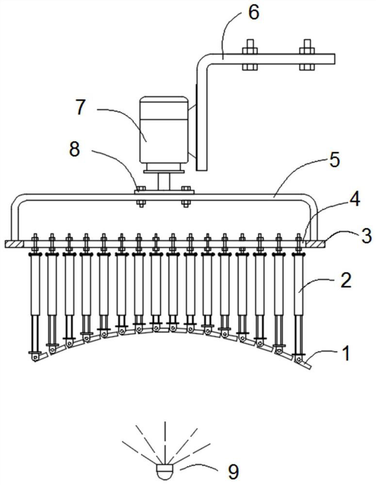
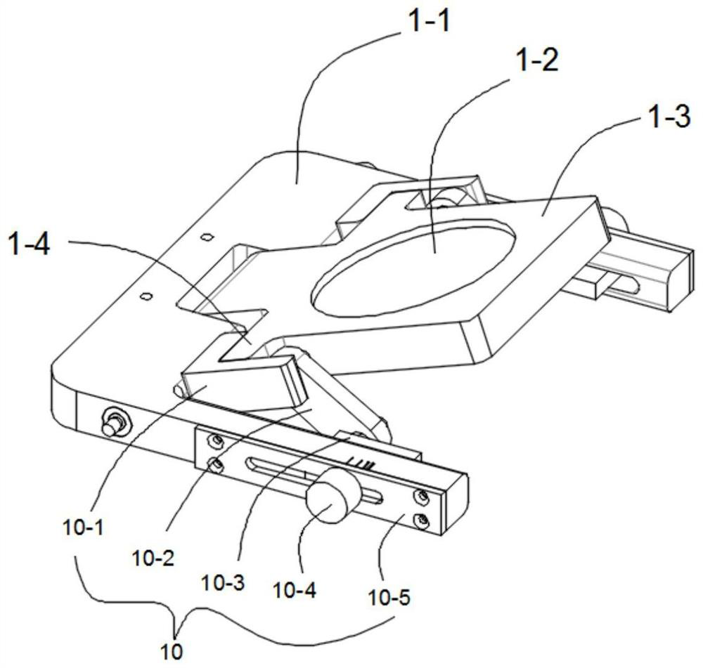
[0030] like Figures 1 to 6 As shown in the figure, this embodiment provides a free-form surface coating clamping equipment, which includes a rotatable mounting frame located above, a drive mechanism 7 for driving the mounting frame to rotate above the mounting frame, and the lower part of the mounting frame is evenly distributed in an array There are tooling units with adjustable spacing, and each tooling unit includes a support 2 whose height can be adjusted and an installation mechanism 1 arranged at the end of the support 2 for installing the discrete units of the test plating components. The coating element discrete unit faces the angle adjustment mechanism 10 of the coating evaporation source 9 and has no shadow effect.
[0031] The structure of this embodiment does not require special preparation of trial plating molds, thereby reducing the cost of trial plating. When the discrete unit area is sufficiently small, the equipment can simulate various complex curved surface...
Embodiment 2
[0033] This embodiment is further optimized on the basis of Embodiment 1, specifically:
[0034] The driving mechanism 7 is a servo motor, and the driving mechanism 7 is mounted on the L-shaped bracket 6 , and the L-shaped bracket 6 is provided with a bolt assembly detachably connected to the external support base.
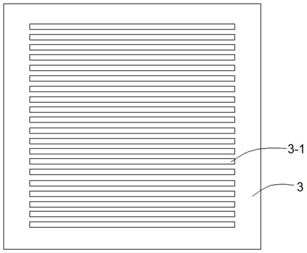
[0035] The mounting frame includes a horizontal mounting plate 3 and a U-shaped bracket 5 arranged on the horizontal mounting plate 3 with an opening facing downward. The two straight edge sections of the U-shaped bracket 5 are fixed on the left and right sides of the horizontal mounting plate 3. The output shaft of the motor is detachably connected to the U-shaped bracket 5 through the fixing plate 8, and the horizontal mounting plate 3 is provided with a plurality of strip holes 3-1 at equal intervals for installing the tooling unit.
[0036] The edge of each of the strip holes 3-1 is provided with a scale along the length direction to facilitate precise adjustm...
PUM
 Abstract
Description
Claims
Application Information
 - R&D Engineer
- R&D Manager
- IP Professional
- Industry Leading Data Capabilities
- Powerful AI technology
- Patent DNA Extraction
Browse by: Latest US Patents, China's latest patents, Technical Efficacy Thesaurus, Application Domain, Technology Topic, Popular Technical Reports.
© 2024 PatSnap. All rights reserved.Legal|Privacy policy|Modern Slavery Act Transparency Statement|Sitemap|About US| Contact US: help@patsnap.com