
A hook anti-rotation positioning device

A positioning device and anti-rotation technology, applied in transportation and packaging, load hanging components, wind power generation, etc., can solve the problems of low adjustment efficiency, inconvenient adjustment, automatic adjustment of hooks, etc.

Active Publication Date: 2022-08-09
HENAN NORMAL UNIV
View PDF8 Cites 0 Cited by
  • Summary
  • Abstract
  • Description
  • Claims
  • Application Information

AI Technical Summary

Problems solved by technology

[0007] In order to overcome the shortcomings that the hook in the prior art cannot automatically adjust the state of the hook when lifting and lowering the goods, the adjustment efficiency is low, and it is inconvenient to adjust and hook the goods when the goods are large in size, the technical problem is as follows: : Provide a hook anti-rotation positioning device that can automatically adjust the state of the hook when lifting and lowering the goods, and is convenient for hooking the goods

Method used


Image

  • A hook anti-rotation positioning device
  • A hook anti-rotation positioning device
  • A hook anti-rotation positioning device

Examples


Embodiment 1

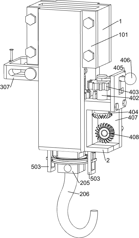
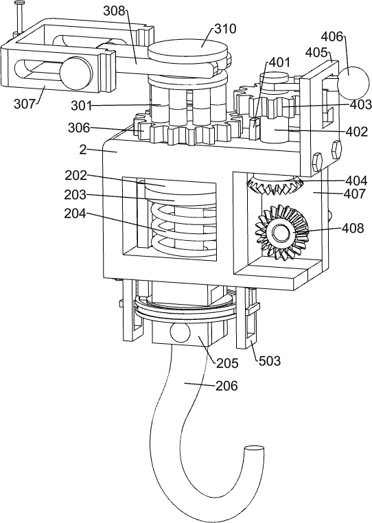
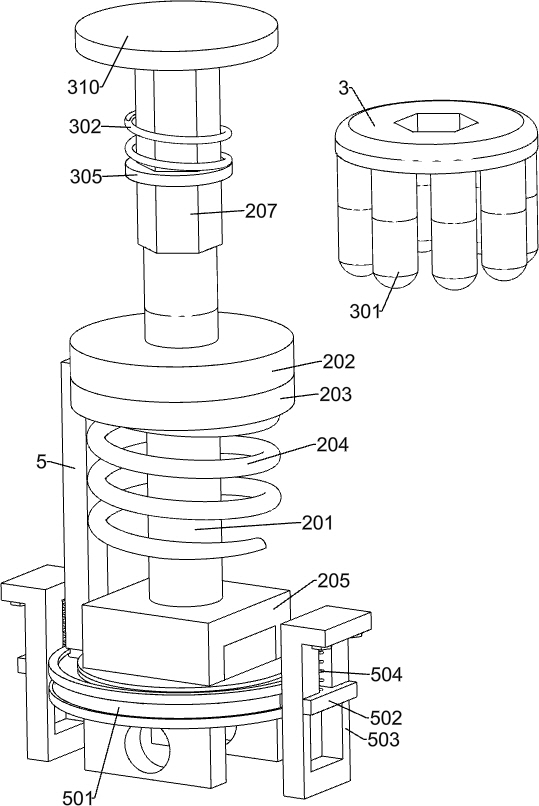
[0035] A hook anti-rotation positioning device, such as Figure 1-7As shown, it includes a connecting seat 1, a connecting plate 101, a bearing seat 2, a driving shaft 201, a first pressure plate 202, a second pressure plate 203, a return spring 204, a connecting block 205, a hook 206, a hexagonal prism 207, a limit For the position plate 303 and the limiting mechanism, the connecting base 1 is symmetrically fixed with two connecting plates 101, and the two connecting plates 101 are jointly fixed with the bearing seat 2, and the bearing seat 2 is rotatably connected with the driving shaft 201, the driving shaft A first pressure plate 202 is fixedly connected to the 201, a second pressure plate 203 is connected to the driving shaft 201, and a return spring 204 is sleeved on the driving shaft 201 for pushing the first pressure plate 202 and the second pressure plate 203 to reset upward. A connecting block 205 is fixed on the shaft 201, and a hook 206 for lifting goods is rotatab...

Embodiment 2

[0042] On the basis of Example 1, as figure 2 , Figure 4 and Figure 7 As shown in the figure, it also includes an adjustment mechanism that can drive the limit gear 306 to rotate when the goods are hoisted. The adjustment mechanism is installed on the bearing base 2, and the adjustment mechanism includes an adjustment spring 4, an adjustment rod 401, an adjustment shaft 402, and an adjustment gear. 403, the upper bevel gear 404, the adjustment guide plate 405, the adjustment handle 406, the adjustment connection plate 407, the lower bevel gear 408 and the adjustment handle 409, the limit plate 303 is slidingly connected with the bearing base 2 and connected with a plurality of adjustment springs 4, The limit plate 303 is fixedly connected with an adjustment post 401 slidably connected to the bearing base 2 , and the adjustment post 401 is used to drive the limit disc 303 to move downward. The bearing base 2 is slidably connected with an adjustment shaft 402 , and the adjus...

Embodiment 3

[0045] On the basis of Example 2, as figure 2 and image 3 As shown, it also includes a restricting mechanism that can restrict the up and down swing of the hook 206. The restricting mechanism is connected to the second pressure plate 203. The restricting mechanism includes a restricting post 5, a restricting ring 501 and a buffer guide assembly. The second pressure plate 203 is connected to the second platen 203. The first pressure plate 202 is rotatably connected, the second pressure plate 203 is fixedly connected with a restricting post 5, and the restricting post 5 is connected with a restricting ring 501 for restricting the swing of the hook 206, and the restricting ring 501 is sleeved on the connecting block 205, The limit ring 501 is connected with a buffer guide assembly for buffering and guiding it; when the driving shaft 201 moves downward, it will drive the first pressure plate 202 and the second pressure plate 203 to move downward, thereby driving the limit ring t...


PUM


Abstract

The invention relates to a positioning device, in particular to a hook anti-rotation positioning device. The technical problem is: to provide a hook anti-rotation positioning device that can automatically adjust the hook state when lifting and laying down the goods, and is convenient for hooking the goods. The technical scheme is: an anti-rotation positioning device for a hook, comprising a connecting seat, a connecting plate, a bearing seat, a driving shaft, a first pressing plate, a second pressing plate, etc.; two connecting plates are symmetrically fixed on the connecting seat , the two connecting plates are jointly fixed with a bearing seat, the bearing seat is rotatably connected with a driving shaft, a first pressure plate is fixed on the driving shaft, a second pressure plate is connected on the driving shaft, and a sleeve on the driving shaft is used to push Return springs that return the first pressure plate and the second pressure plate upward. Through the cooperation of the hook, the connecting block, the limiting mechanism, the limiting groove and the hexagonal column, the disadvantages of the prior art, such as the inability of the hook in the prior art to automatically adjust the state of the hook when hoisting and putting down the goods, and the low adjustment efficiency are overcome. .

Description

technical field [0001] The invention relates to a positioning device, in particular to a hook anti-rotation positioning device. Background technique [0002] The hook is one of the most common spreaders in machinery. [0003] In the hoisting operation in the prior art, in order to facilitate the hanging of the goods on the hook, the hook is usually installed on the hoisting machine in a rotational connection, and the hook can swing, and the hook can be rotated by rotating the hook. The position of the quasi-goods, the swinging hook is convenient for the hook to hook the goods; however, when the rotating hook is hoisting the goods, because some goods are heavier or larger, it is easy to drive the hoist during the moving process. The hook rotates, which makes the goods unstable during transportation, which can easily cause the goods to collide with surrounding facilities, or even bruise the staff, which makes the lifting operation with a certain risk factor even more hidden. ...

Claims


Application Information

Patent Timeline
Patent Type & Authority Patents(China)
IPC IPC(8): B66C1/34B66C13/08B66C13/06
CPCB66C1/34B66C13/08B66C13/06Y02E10/72
Inventor 耿直白佳欣王子璇班慧妤王灿曹钰晨徐靖泽赵若昕梁萌杨林
Owner HENAN NORMAL UNIV
Learn More