Home circuit fault self-test switch

A technology of circuit faults and electric gates, applied in the field of electric gates, can solve problems such as lack of tools, cumbersome circuits, and dangers of electric gates, so as to facilitate maintenance work, reduce the difficulty of detection, and prevent leakage

Active Publication Date: 2022-08-02
中测智联(深圳)科技有限公司
View PDF5 Cites 0 Cited by
  • Summary
  • Abstract
  • Description
  • Claims
  • Application Information

AI Technical Summary

Problems solved by technology

[0004] When there is a problem with the circuit at home, it is necessary to check the switch, so as to rule out whether there is a problem with the circuit or the switch. However, when troubleshooting the switch, it is necessary to use specific tools. Most households are basically not equipped with tools. In turn, it is necessary to call an electrician for investigation and maintenance, which increases the complexity of circuit detection; at the same time, when repairing household circuits, it is necessary to disconnect the electric switch to perform maintenance. If there is a problem with the electric switch this time, it may leak. When family members operate, they may get an electric shock without accident, and the electric switch exposed in daily life also has certain danger.

Method used


Image

  • Home circuit fault self-test switch
  • Home circuit fault self-test switch
  • Home circuit fault self-test switch

Examples


Embodiment 1

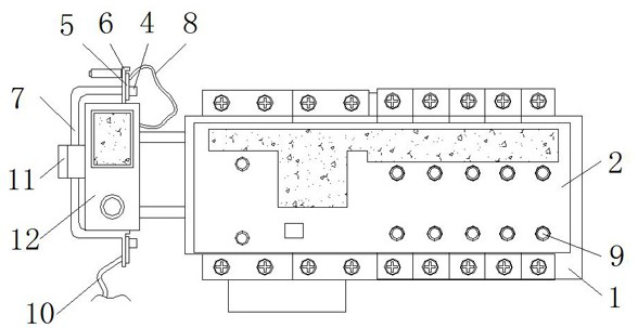
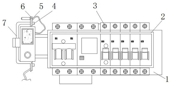
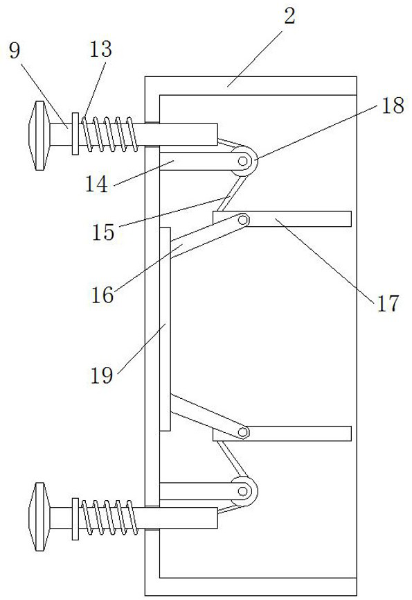
[0034] Example 1, as Figure 1-5 As shown, when the home circuit needs to be repaired, the pull rod 9 is first pulled, so that the pull rod 9 extends from the interior of the insulating chamber 2, and the pull rod 9 drives the spring 13 to extend during the extension process, and pulls the connecting rope 15 at the same time. The connecting rope 15 is made to slide along the spring 13, and then the connecting rope 15 pulls the hinge plate 17 to turn down, so as to toggle the switch of the electric switch and disconnect the circuit in the home, thus avoiding direct contact with the electric switch and effectively preventing the situation of electric shock Occurs, after the circuit maintenance is completed, pull the rod 9 at the bottom, and then drive the hinge plate 17 at the bottom to turn up, so that the switch of the electric switch is pulled up, so that the circuit is reconnected.

Embodiment 2

[0035] Example 2, as Figure 1-5 As shown in the figure, when the electric switch needs to be tested, first take out the handle 7 from the inside of the clip 11, and then fit the contact piece 4 on the top of the handle 7 with the screw 3 on the top of the electric switch 1, and then hold the Fit the contact piece 4 at the bottom of 7 with the screw 3 at the bottom of the switch 1, and then press the switch on the test table 12. By checking the data on the table 12, you can observe whether the switch 1 is damaged, and then conduct self-test.

[0036] Working principle: when the home circuit needs to be repaired, first pull the pull rod 9, so that the pull rod 9 extends from the interior of the insulating chamber 2, the pull rod 9 drives the spring 13 to extend during the extension process, and pulls the connecting rope 15 at the same time. The connecting rope 15 is made to slide along the spring 13, and then the connecting rope 15 pulls the hinge plate 17 to turn down, so as t...


PUM


Abstract

The invention discloses a home circuit fault self-checking electric switch, which includes an electric switch, an insulating compartment is arranged at one end of the electric switch, a plurality of groups of pull rods are evenly arranged on one side of the insulating cabin, the outer side of the pull rod is provided with a spring, and the pull rod is provided with a spring. One end of the insulation chamber extends to the interior of the insulating chamber, and one end of the insulating chamber is provided with an anti-shock assembly; the present invention uses the cooperation of a spring, a mounting plate, a connecting rope, a fixing plate, a hinge plate, a pulley and a pull rod, when a problem occurs in the circuit. , the circuit can be disconnected without directly touching the internal gate, thereby preventing the leakage of the gate, preventing the user from directly touching the gate without protection and causing electric shock, thereby effectively improving the protection. At the same time, it can also play an effective protective effect in daily life to prevent accidents from accidentally touching the switch in daily life.

Description

technical field [0001] The invention relates to the technical field of electric switches, in particular to a home circuit fault self-checking electric switch. Background technique [0002] The switch refers to a relatively large power switch, a leakage protection switch, also known as a knife, which is a switching device that is mainly used for "isolating the power supply, switching off operation, and connecting and cutting off small current circuits" without arc extinguishing function. In the open position, there is an insulation distance between the contacts that meets the specified requirements and an obvious disconnection mark. When in the closed position, it can carry the current under normal circuit conditions and the current under abnormal conditions within the specified time. Switchgear, and When there is a problem with the home circuit, the switch needs to be tested. [0003] The current switch has the following inconveniences: [0004] When there is a problem wit...

Claims


Application Information

Patent Timeline
Patent Type & Authority Patents(China)
IPC IPC(8): H01H3/02H01H3/46H01H9/54G01R31/327
CPCH01H3/02H01H3/46H01H9/54G01R31/327
Inventor 王蕾
Owner 中测智联(深圳)科技有限公司
Why Eureka
Try Eureka