Battery replacement bracket for power battery of electric vehicle

A technology of electric vehicles and electric brackets, which is applied in the direction of electric vehicles, battery pack components, circuits, etc., can solve the problems of difficult replacement operations, heavy weight, and difficult full-box battery replacement applications, so as to improve wear resistance and The effect of low temperature resistance

Pending Publication Date: 2022-06-07
王密琳
View PDF0 Cites 0 Cited by
  • Summary
  • Abstract
  • Description
  • Claims
  • Application Information

AI Technical Summary

Problems solved by technology

[0006] However, due to the strength of the battery box and the structural stress deformation of the vehicle chassis, the full-box battery replacement mode is currently only suitable for small-scale vehicle applications, and power battery explosion accidents also occur from time to time
However, the power battery box of a large electric vehicle is currently more difficult to realize the application of a full box battery replacement. The main reason is that if the battery box of a large electric vehicle is designed as a whole box, it will be large in size and heavy in weight, making it difficult to replace the operation.
The most critical reason is that most of the large vehicles are commercial vehicles with heavy loads and are frequently used. The stress deformation of the vehicle structure will cause mechanical interference to the power battery box arranged on the chassis, and may even cause accidents such as combustion and explosion of the power battery.

Method used


Image

  • Battery replacement bracket for power battery of electric vehicle
  • Battery replacement bracket for power battery of electric vehicle
  • Battery replacement bracket for power battery of electric vehicle

Examples


Embodiment

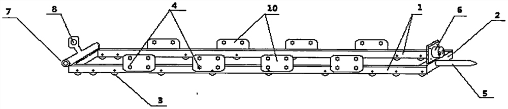
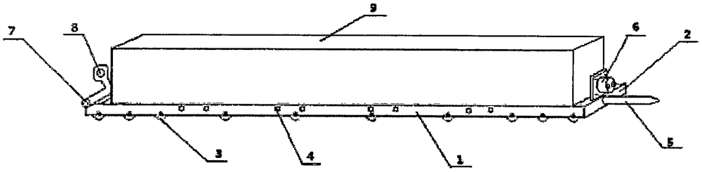
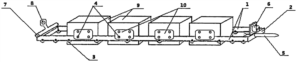
[0027] Embodiment A structure of an electric vehicle battery swap bracket is shown in the appendix. figure 1 shown.

[0028] Its structure is designed and manufactured as follows: a rectangular frame structure is welded by two longitudinal beams (1) and two transverse beams (2), wherein the longitudinal beam (1) is a C-shaped steel profile, with the C port facing down, and rows of load-bearing are installed. The rollers (3), in practice, the distribution of the rollers (3) should be closely arranged at both ends in order to reduce noise and durability. Positioning and mounting holes (4) of the power battery box (9) are also arranged on the longitudinal beam (1), and the number and spacing of the holes are specifically set by the number and spacing of the battery boxes. One end of the bracket is installed with a vertical positioning pin (5) and an electrical connector (6), and the other end of the bracket is installed with a horizontal transverse positioning pin hole (7) and a...


PUM


Abstract

A battery changing bracket for an electric automobile relates to the technology of quickly changing power batteries in the field of energy complementation of the electric automobile, and is mainly structurally characterized in that the bracket is a square or rectangular bracket formed by combining two (more than two) longitudinal beams and two (more than two) cross beams; wherein the longitudinal beam is provided with a bearing roller, a positioning mounting hole for arranging a power battery box and a reinforcing vertical plate, the reinforcing vertical plate is provided with a fixed battery box, one end of the bracket is provided with a longitudinal positioning pin and an electric appliance connector, and the other end of the bracket is provided with a transverse positioning pin hole and a handle for pushing and pulling a force applying point of the bracket. According to the battery replacing bracket for the electric vehicle, through the structural design that the longitudinal positioning pin is installed at one end of the bracket and the reinforcing vertical plate is installed on the longitudinal beam, two sets of methods capable of compositely relieving the damage influence of the stress of a chassis of the whole vehicle on a battery box are achieved, and the whole-box type quick battery replacing of the small electric vehicle can be achieved; and a large-scale electric vehicle can also realize whole-box type rapid battery replacement.

Description

Technical field: [0001] Rapid replacement power battery technology in the field of electric vehicle energy supplementation. Background technique: [0002] After nearly ten years of rapid development of electric vehicles, the electric vehicle market side of the charging and energy supplement mode has increasingly highlighted many drawbacks. Fast charging still takes more than half an hour. The charging efficiency is low, but the cost of facilities is very high. The key is that it is not safe to affect the life of the battery, and the power grid is heavily burdened. In short, the simple charging mode cannot meet the healthy development of the industry. [0003] In recent years, after several electric vehicle companies in China have explored the way to quickly replace the power battery to replenish energy, it has been proved that rapid battery replacement and energy replenishment can effectively solve the above-mentioned various drawbacks, and it is a good electric vehicle. Th...

Claims


Application Information

Patent Timeline
IPC IPC(8): B60L53/80H01M50/244H01M50/249H01M50/209
CPCB60L53/80Y02T10/7072
Inventor 王密琳
Owner 王密琳
Why Eureka
Try Eureka