Rotating shaft structure for glasses and use method of rotating shaft structure

A shaft structure and glasses technology, which is applied in the field of glasses, can solve the problems of uncomfortable wearing of AR glasses

Pending Publication Date: 2022-06-03
SHANGHAI CHENXING ELECTRONICS SCI & TECH CO LTD
View PDF6 Cites 0 Cited by
  • Summary
  • Abstract
  • Description
  • Claims
  • Application Information

AI Technical Summary

Problems solved by technology

[0004] The purpose of the present invention is to overcome the defects of the prior art, to provide a rotating shaft structure for glasses and its use method, which solves the problem of uncomfortable wearing of AR glasses, through which the rotating shaft structure endows the temples with elasticity, which can be adapted to different heads. The clamping force of the temples on the user's head can also fix the glasses on the user's head, share part of the weight of the glasses, prevent the weight of the glasses from fully acting on the bridge of the user's nose, and improve the comfort and experience of the glasses

Method used


Image

  • Rotating shaft structure for glasses and use method of rotating shaft structure
  • Rotating shaft structure for glasses and use method of rotating shaft structure

Examples


specific Embodiment approach

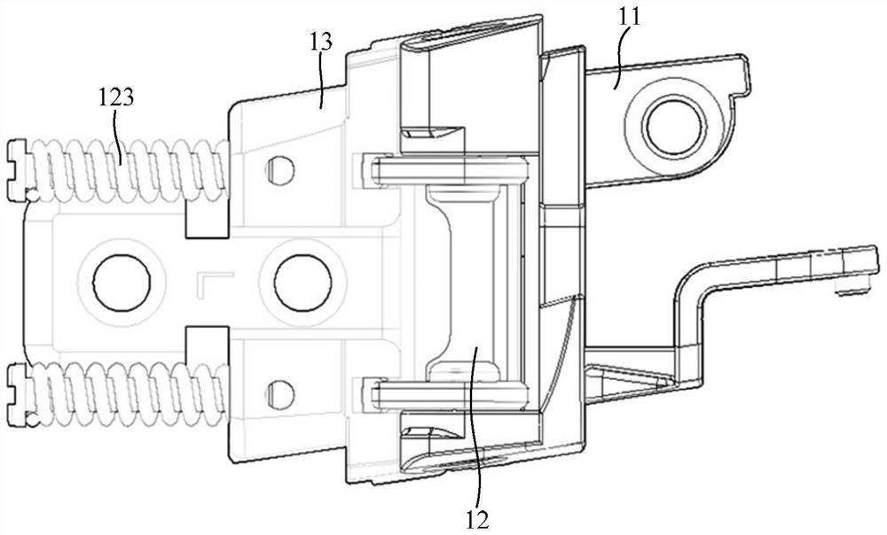
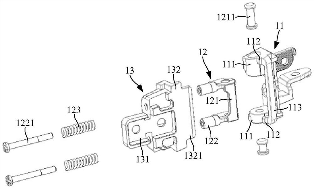
[0048] The fixing frame 11 is fixedly connected with one end of the frame body. At this time, the protruding part 112 faces the direction away from the other end of the frame body, and the connecting piece 13 is fixedly connected with the temple. The connecting piece 13 can be inserted in the temple and pass through Fixed bolt connection;

[0049] When the temples are turned inward, that is, the two temples are rotated in the direction of approaching each other, the clamping plate 132 moves along the arc of the fixing frame 11 away from the protruding part 112, so that the temples can be parallel to the frame body. And fit to the frame body, so as to facilitate the storage of glasses;

[0050] When the temples are turned outward, that is, the two temples are rotated in a direction away from each other, the clamping plate 132 moves along the arc of the fixing frame 11 in a direction close to the protruding portion 112. During this process, the connecting plate 131 does not move...


PUM


Abstract

The invention relates to a rotating shaft structure for glasses and a use method thereof, and the rotating shaft structure comprises a fixed frame which is provided with a part protruding outwards to form a protruding part; a spring is fixedly arranged at one end, far away from the fixed frame, of the rotating part; the connecting piece is mounted on the rotating piece in a position-adjustable manner and is positioned on one side, close to the fixed frame, of the spring, a clamping plate is formed on the connecting piece corresponding to the convex extension part, and the convex extension part pushes the clamping plate by rotating the glasses legs so as to drive the connecting piece to move towards the direction far away from the fixed frame and extrude the spring, so that the spring generates resilience force on the connecting piece. The problem that AR glasses are uncomfortable to wear is effectively solved, elastic force is given to the glasses legs through the rotating shaft structures, the glasses legs can adapt to users with different head circumferences, the glasses can be fixed to the heads of the users through clamping force of the glasses legs to the heads of the users, part of the weight of the glasses is shared, the situation that the weight of the glasses completely acts on the nose bridges of the users is avoided, and the user experience is improved. And the comfort and experience of the glasses are improved.

Description

technical field [0001] The invention relates to the field of glasses, in particular to a rotating shaft structure for glasses and a method for using the same. Background technique [0002] With the increasing demand for AR glasses, more and more types and uses of AR glasses, the application potential of AR augmented reality is huge, and it can be widely used in military, medicine, manufacturing and maintenance, entertainment and many other fields. [0003] Due to the existing designs on the market, the AR glasses are large in shape and too heavy, which are uncomfortable to wear, and even the temples cannot be folded back, which directly affects the wearing comfort and experience of AR glasses. SUMMARY OF THE INVENTION [0004] The purpose of the present invention is to overcome the defects of the prior art, to provide a rotating shaft structure for glasses and a method of using the same, so as to solve the problem that AR glasses are uncomfortable to wear. The glasses can...

Claims


Application Information

Patent Timeline
IPC IPC(8): G02B27/01
CPCG02B27/0176G02B2027/0178
Inventor 赵建伟
Owner SHANGHAI CHENXING ELECTRONICS SCI & TECH CO LTD
Why Eureka
Try Eureka