
Laser engraving method for editable curved surface 3D texture

A laser engraving, 3D technology, applied in 3D image processing, 3D modeling, laser welding equipment and other directions, can solve the problems of increasing the difficulty of part surface texture design, inability to obtain texture graphics, part rotation or deflection, etc. Guaranteed best quality, editability, combined effects

Inactive Publication Date: 2022-06-03
镭泽精密制造(苏州)有限公司
View PDF1 Cites 0 Cited by
  • Summary
  • Abstract
  • Description
  • Claims
  • Application Information

AI Technical Summary

Problems solved by technology

Compared with the method of laser five-axis interpolation to achieve texture processing, the method used by this etching system is much higher in efficiency and accuracy, but this method also has some defects: 1. Parts with surface texture characteristics to be processed will undoubtedly increase the difficulty of designing the surface texture of the part, and will greatly limit the flexible manufacturing of the part when the texture changes
2. Due to the processing needs of parts, especially large-sized parts, it is inevitable to encounter the problem of rotation or deflection of parts (or scanning galvanometer), which will cause angle changes in the processed graphics, thus Unable to get accurate texture graphics

Method used


Image

  • Laser engraving method for editable curved surface 3D texture
  • Laser engraving method for editable curved surface 3D texture

Examples


Embodiment Construction

[0023] The present invention will be described in detail below with reference to the various embodiments shown in the accompanying drawings, but it should be noted that these embodiments do not limit the present invention. Equivalent transformations or substitutions all fall within the protection scope of the present invention.

[0024] It should be noted that the embodiments in the present application and the features of the embodiments may be combined with each other in the case of no conflict. In order to facilitate understanding of the present invention, the present invention will be described more fully hereinafter with reference to the related drawings. The preferred embodiments of the invention are shown in the accompanying drawings. However, the present invention may be embodied in many different forms and is not limited to the embodiments described herein. Rather, these embodiments are provided so that a thorough and complete understanding of the present disclosure ...


PUM


Abstract

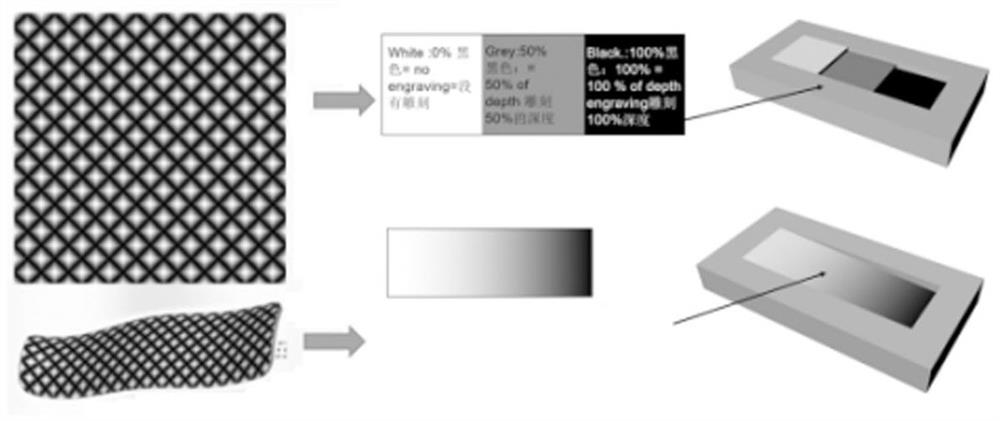
The invention provides a laser engraving method for editable curved surface 3D textures, laser equipment comprises a five-axis numerical control platform, a laser engraving system, a PC industrial personal computer and CAM software installed in a WINDOS operating system of the PC industrial personal computer, and the laser engraving method comprises the following steps: S1, the CAM software adopts a designed and processed high-quality gray-scale texture picture, and the processed high-quality gray-scale texture picture is subjected to laser engraving; the texture data are laid on the 3D model curved surface of the machined part through UVN direction curved surface control characteristics, and a 3D texture file is generated; s2, generating a machined part 3D model with 3D textures on the curved surface through a gray-scale value substitution algorithm; s3, generating a final vector diagram file by editing and setting the gray-scale value; and S4, controlling a five-axis numerical control platform to cooperate with a laser engraving system to perform numerical control displacement through a final program generated by the CAM software, processing according to a vector diagram file designed or edited by the CAM software, and engraving 3D textures. Through the disclosure of the invention, the editability of the 3D texture can be realized.

Description

technical field [0001] The invention relates to the technical field of laser engraving, and more particularly to a laser engraving method capable of editing curved 3D textures. Background technique [0002] As an advanced manufacturing technology, laser processing technology has high energy density, good collimation, and focusing spot can often achieve micron-level precision. Therefore, a specific laser processing head is used to replace the tool in traditional machining, and the high energy of the focused laser is used to scan and mark the spatial curve or curved surface through the three-dimensional interpolation positioning function of the multi-axis motor to realize the modification of the material. Or removal has become an important means in the field of high-precision machining. [0003] Huazhong University of Science and Technology Cao Yu et al proposed "a laser processing method and device suitable for complex curved surfaces", the patent number is CN102151984B. In...

Claims


Application Information

Patent Timeline
Patent Type & Authority Applications(China)
IPC IPC(8): B23K26/362B23K26/70G06F30/17G06F30/20G06T15/04G06T17/00G06T19/20
CPCB23K26/362B23K26/70G06F30/17G06F30/20G06T15/04G06T17/00G06T19/20G06T2219/2012
Inventor 张鸿飞李有盛
Owner 镭泽精密制造(苏州)有限公司
Learn More