


Quick Research
Generate reliable direction feasibility study reports for your R&D in just a few steps.

Technical Q&A
Discover and master advanced knowledge NOW. Basics, ideas, possibilities, all at once.

Find Solutions
As an expert in R&D theories, this can generate solutions to your technical problems instantly.

Evaluate Feasibility
Analyze your overall solution with one click, know your potential R&D risks in advance.

Monitor Landscape
Get weekly tech updates, stay abreast of the latest tech innovations and key insights.
Intelligent lamp pole power dynamic distribution method and system
A technology of dynamic allocation and light poles, which is applied in the direction of electric vehicle charging technology, climate sustainability, and AC network voltage adjustment. The effect of avoiding and reducing resource consumption
- Summary
- Abstract
- Description
- Claims
- Application Information
AI Technical Summary
Problems solved by technology
Method used
Image


Examples
Embodiment 1
[0043] This embodiment proposes a method for dynamically distributing the power of smart light poles, such as figure 1 As shown, it is a flowchart of the method for dynamically distributing the power of the smart light pole in this embodiment.
[0044] The method for dynamic power distribution of smart light poles proposed in this embodiment includes the following steps:
[0045] S1. When the light pole starts to work, the parameters of the current distribution transformer and distribution box are collected.
[0046] In this embodiment, the collected parameters of the current distribution transformer and distribution box include the real-time power P of the distribution transformer. t and the real-time power P of the distribution box ct , where the real-time power of the distribution box is the sum of the real-time lighting power of X light poles and the real-time power of Y charging piles.
[0047] S2, according to the real-time power of the distribution transformer and th...
Embodiment 2
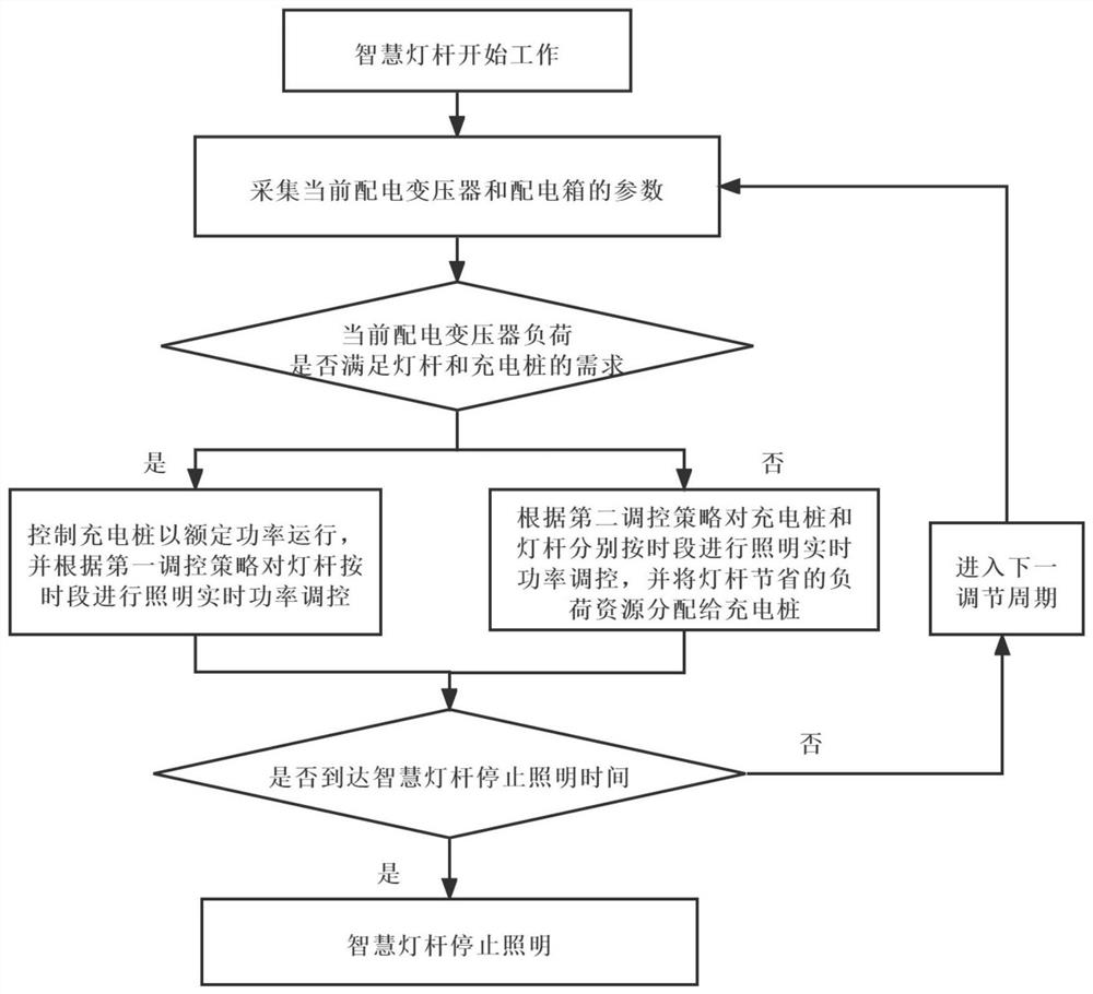
[0083] This embodiment makes improvements on the basis of the dynamic power distribution method for smart light poles proposed in Embodiment 1. like figure 2 As shown, it is a flowchart of the method for dynamically distributing the power of the smart light pole in this embodiment.
[0084] The method for dynamic power distribution of smart light poles proposed in this embodiment is further provided with the following steps: every time an adjustment cycle is entered, re-according to the real-time power of the distribution transformer and the distribution box, it is judged whether the current load of the distribution transformer meets the requirements of the light pole. According to the needs of lighting and charging piles, it is re-selected to control the power of the lamp pole lighting or / and the charging piles according to the first regulation strategy or the second regulation strategy according to the time period.
[0085] In the specific implementation process, it is ass...
Embodiment 3
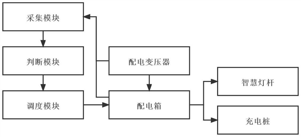
[0092] This embodiment proposes a system for dynamic power distribution of smart light poles, which is applied to the method for dynamic power distribution of smart light poles proposed in Embodiment 1. like Figures 3 to 4 As shown, the structure diagram of the smart light pole power dynamic distribution system of this embodiment.
[0093] The smart light pole power dynamic distribution system proposed in this embodiment includes a smart light pole, a charging pile installed in the charging pile installation area of the smart light pole, a distribution transformer and a distribution box for power distribution; The connected acquisition module, the judgment module and the dispatching module, wherein the output end of the dispatching module is connected with the control end of the distribution box.
[0094] Among them, the acquisition module is used to collect the parameters of the current distribution transformer and distribution box, the parameters collected by the acquisi...
PUM
 Abstract
Description
Claims
Application Information
 - R&D Engineer
- R&D Manager
- IP Professional
- Industry Leading Data Capabilities
- Powerful AI technology
- Patent DNA Extraction
Browse by: Latest US Patents, China's latest patents, Technical Efficacy Thesaurus, Application Domain, Technology Topic, Popular Technical Reports.
© 2024 PatSnap. All rights reserved.Legal|Privacy policy|Modern Slavery Act Transparency Statement|Sitemap|About US| Contact US: help@patsnap.com