Eureka AIR delivers breakthrough ideas for toughest innovation challenges, trusted by R&D personnel around the world.

Safety system for energy storage battery container

A safety system and energy storage battery technology, applied in the field of safety systems, can solve the problems that the coolant is difficult to directly act on the high temperature area, the battery is bulged and deformed, and it is difficult to isolate and extinguish the fire, so as to avoid secondary safety problems and reduce the dosage. , the effect of reducing the concentration of flammable gases

Pending Publication Date: 2022-05-27
INST OF ELECTRICAL ENG CHINESE ACAD OF SCI +1
View PDF0 Cites 0 Cited by
  • Summary
  • Abstract
  • Description
  • Claims
  • Application Information

AI Technical Summary

Problems solved by technology

Energy storage systems usually use chemical batteries, and batteries have their own oxidants and reductants. Once a fire occurs unexpectedly, it is difficult to extinguish it through chemical suppression and suffocation. Batteries are densely arranged in the system. Modules, battery packs, batteries Clusters and battery racks are fixedly arranged in the container. When local high temperature or burning occurs, the battery will bulge and deform, and it is difficult to separate it from the container to isolate and extinguish the fire. It is also difficult for the coolant to directly act on the high temperature area. Short-term intense heat release is easy to spread the fire

Method used


Image

  • Safety system for energy storage battery container
  • Safety system for energy storage battery container
  • Safety system for energy storage battery container

Examples


Embodiment Construction

[0042] The present invention will be further described below with reference to the accompanying drawings and embodiments.

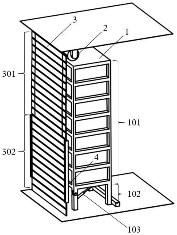
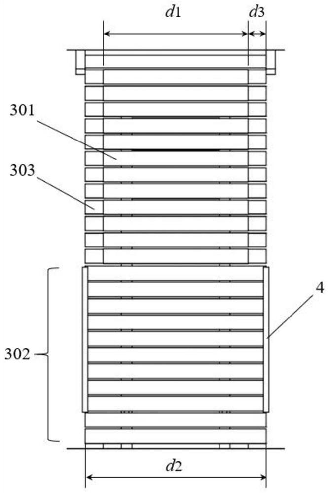
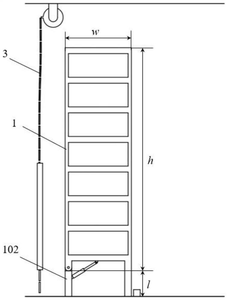
[0043] figure 1 It is a three-dimensional schematic diagram of a safety system for an energy storage battery container according to the present invention. A safety system for an energy storage battery container includes a control device, a battery rack 1 , a safety buffer door, and a sensor arranged in the battery box. The safety buffer door includes a winding motor (not shown in the figure), a reel 2 , a rolling shutter door panel 3 , a door frame (not shown in the figure) and a limiting portion 4 .

[0044] The winding motor is connected with the reel 2 to rotate the reel 2. The reel 2 is connected with the upper end of the rolling shutter door panel 3, and the rolling shutter door panel 3 includes an upper rigid strip 301 and a lower rigid strip 302. Normally, when the reel 2 rotates, the rolling shutter door panel 3 is wound on the reel 2 to open th...


PUM


Abstract

The invention provides a safety system for an energy storage battery container. The safety system comprises a control device, a battery rack, a safety buffer door and a sensor arranged in a battery box. When the sensor detects that a battery in the battery box breaks down, the sensor transmits a signal to the control device, and the control device starts the driving device of the battery rack to enable the bendable supporting legs of the battery rack to bend, so that the battery rack topples towards a roller shutter door plate of the safety buffer door. The rigid strip on the lower portion of the roller shutter door plate plays a role in buffering the toppled battery rack under the keeping of the limiting part, and when the upper end of the roller shutter door plate is broken under the acting force of the battery rack, the roller shutter door plate is separated from the constraint of the limiting part, so that the battery rack is poured out of the container. The battery rack is triggered to be separated from the container in a non-manual mode, the fire fighting risk and difficulty are reduced, and fire spreading and expanding can be rapidly restrained.

Description

technical field [0001] The invention relates to the field of energy storage batteries, in particular to a safety system for an energy storage battery container. Background technique [0002] In recent years, with the continuous development of the energy storage market, the fire safety issues of energy storage systems have become increasingly prominent. The energy storage system usually uses chemical batteries, and the batteries have their own oxidants and reducing agents. Once a fire occurs accidentally, it is difficult to put out the fire through chemical suppression and suffocation. Batteries are densely arranged in the system, with modules, battery packs, batteries The form of clusters and battery racks are fixed in the container. When local high temperature or combustion occurs, the battery will swell and deform, and it is difficult to separate it from the container for isolation and fire fighting. It is also difficult for the coolant to directly act on the high temperat...

Claims


Application Information

Patent Timeline
Patent Type & Authority Applications(China)
IPC IPC(8): H01M50/244H01M50/251H01M50/572H01M10/48E06B9/08
CPCH01M50/244H01M50/251H01M50/572H01M10/482H01M10/488E06B9/08Y02E60/10
Inventor 何颖源侯凯袁晓东张彬陈永翀
Owner INST OF ELECTRICAL ENG CHINESE ACAD OF SCI
Why Eureka
Eureka Blog
Learn More