Elevator dragging method and equipment

A technology for elevators and equipment, which is applied to elevators, lifting equipment in mines, sustainable buildings, etc., can solve the problems of high operating noise, reduced safety and reliability of elevators, and high energy consumption of elevators, so as to reduce the number of cycles and quantity, reduce The risk of cage shifting and the effect of improving ride comfort

Pending Publication Date: 2022-05-27
浙江班门机械科技有限公司
View PDF0 Cites 0 Cited by
  • Summary
  • Abstract
  • Description
  • Claims
  • Application Information

AI Technical Summary

Problems solved by technology

[0002] At present, construction elevators are generally located outside buildings, relying on standard joints to guide and support people or goods to move up and down. The outdoor elevator is greatly affected by the weather, and is generally directly driven by hoisting wire rope or rack and pinion. The current domestic use Basically, they are rack and pinion construction elevators (SC type construction elevators). The elevator has high energy consumption and high operating noise. Since the standard section and the building body are often connected softly, the standard The increase in the guide deviation of the joints reduces the safety and reliability of the elevator; it is prone to risks such as instability and tipping, and the hanging cage falls to the top; the entire equipment is outdoors, and the requirements for the surface protection of the equipment itself are also high
[0003] There is also a kind of construction hoist located in the elevator shaft of the building, which adopts the traction transmission of the traction machine installed under the way, the rope winding ratio is 1:1, and the traction machine is a three-phase asynchronous geared traction machine. The efficiency of the traction machine is low, and the energy consumption is high; since the brake is located between the motor and the gearbox, the braking performance of the traction machine is also weak, and the upward overspeed protection of the cage needs to be realized with the help of a complex mechanism
[0004] There is also a construction hoist located in the elevator shaft of the building, which adopts the traction transmission of the traction machine bottom pit installation method, the rope winding ratio is 2:1, and the traction machine is a permanent magnet synchronous gearless traction machine. There are hanging cages and counterweights on both sides. The weight of the system acts on the traction machine, and the main shaft bears a large load, which has a great impact on the life of the traction machine bearings. This installation method also requires a large hoistway area , the hoistway efficiency utilization rate is not high, and the number of steel wire ropes that need to be configured is large; in addition, the traction machine is fixed in the bottom pit, and the water accumulation and humid environment in the bottom pit have a great impact on its safety and reliability.

Method used


Image

  • Elevator dragging method and equipment
  • Elevator dragging method and equipment
  • Elevator dragging method and equipment

Examples


Embodiment 1

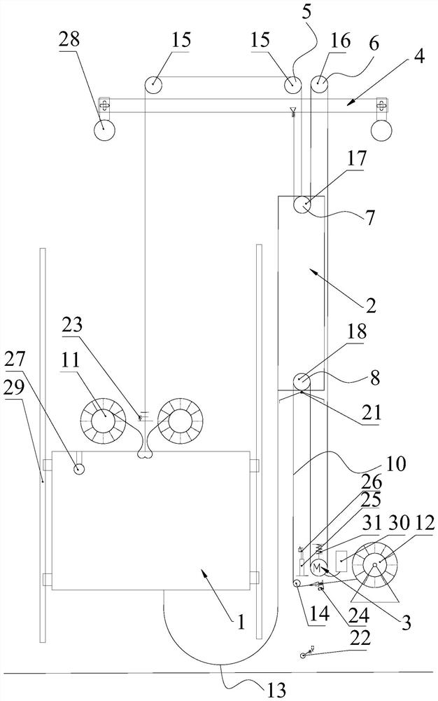
[0037] like figure 1 As shown in the figure, an elevator dragging device includes a cage 1, a counterweight 2, a guide mechanism 29 for the cage and the counterweight to run up and down, a traction machine 3, and a first guide wheel group that are all installed on the hoistway overhead beam 4 5 and the second guide wheel group 6, the cage 1 and the counterweight 2 are located in the hoistway; the traction machine 3 is located on one side of the counterweight 2, and the traction machine 3 can be fixed on the top, bottom, wall or outside of the hoistway , the control system 30 of the traction machine 3 contains an energy feedback device, the traction machine 3 contains a mechanical energy storage device 31, the traction machine is a permanent magnet synchronous gearless or three-phase asynchronous geared form, and the upper end of the counterweight 2 is installed with an upper The wheel set 7, a lower wheel set 8 is installed at the lower end, a locking mechanism 21 is provided ...

Embodiment 2

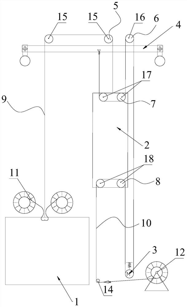
[0051] like image 3 As shown, the difference between this embodiment and Embodiment 1 is that there are two upper wheels 17 and two lower wheels 18 .

Embodiment 3

[0053] like Figure 4 As shown, the difference between this embodiment and Embodiment 1 or 2 is that it also includes a third guide wheel group 19 and a fourth guide wheel group 20, the third guide wheel group 19 is installed on the hoistway sky beam 4, and the fourth guide wheel group The group 20 is installed at the lower part of the hoistway, the upper wheel group 7 includes a plurality of upper wheels 17, the lower wheel group 8 includes a plurality of lower wheels 18, the third guide wheel group 19 includes at least one third guide wheel, and the fourth guide wheel group 20 includes At least one fourth guide wheel; one end of the first traction cable 9 is relatively fixed with the hanging cage 1 and connected with the first code disc 11, and the other end of the first traction cable 9 goes up around the first guide wheel group 5 and then goes down Connected with the counterweight 2; one end of the second traction cable 10 is relatively fixed to the bottom of the hoistway ...


PUM


Abstract

The elevator dragging device comprises a lifting cage, a balance weight, a guide mechanism for the lifting cage and the balance weight to move up and down, a traction machine, a first guide wheel set and a second guide wheel set, the upper end of the balance weight is provided with an upper wheel set, and the lower end of the balance weight is provided with a lower wheel set; one end of the first traction cable is relatively fixed with the cage and is connected with the first coded disc, and the other end of the first traction cable upwards bypasses the first guide wheel group and then is downwards connected with the counterweight; and one end of the second traction cable is relatively fixed with the lower part of the hoistway and is connected with the second coded disc, and the other end of the second traction cable is wound on the traction machine after upwards bypassing the lower wheel set, then upwards wound on the second guide wheel set, downwards wound on the upper wheel set and finally upwards fixed with the hoistway sky beam through a rope head combination. The length of the traction cable and the length of the guide mechanism can be continuously adjusted through the coded disc to meet the height change of a building. And through an indirect driving mode, the cycle frequency and number of the traction cable are reduced, reactive power loss caused by the quality of a traction cable system is reduced, and the operation efficiency is improved.

Description

technical field [0001] The invention relates to construction equipment for construction projects, in particular to equipment for construction elevators in wells, and in particular to methods and equipment for dragging elevators. Background technique [0002] At present, construction elevators are generally located outside the building, relying on standard section guidance and the up and down operation of the cage that supports people or goods. The outdoor elevator is greatly affected by the weather, and is generally directly driven by hoisting wire ropes or gear racks. They are basically rack and pinion construction lifts (SC type construction lifts), which have high energy consumption and high operating noise. Because the standard section and the building body are often softly connected, in strong winds and thunderstorms and large lifting heights, the standard The increase of the section guide deviation reduces the safety and reliability of the elevator; it is prone to risk...

Claims


Application Information

Patent Timeline
IPC IPC(8): B66B15/06B66B15/08B66B15/04B66B17/12B66B5/00
CPCB66B15/06B66B15/08B66B15/04B66B17/12B66B5/0031Y02B50/00
Inventor 彭忠良赵安莉周健
Owner 浙江班门机械科技有限公司
Why Eureka
Try Eureka