New energy automobile battery carrying box
A technology of new energy vehicles and carrying boxes, which is applied in the field of carrying boxes, can solve problems such as battery damage, and achieve the effect of avoiding movement
- Summary
- Abstract
- Description
- Claims
- Application Information
AI Technical Summary
Problems solved by technology
Method used
Image

Examples
Embodiment 1
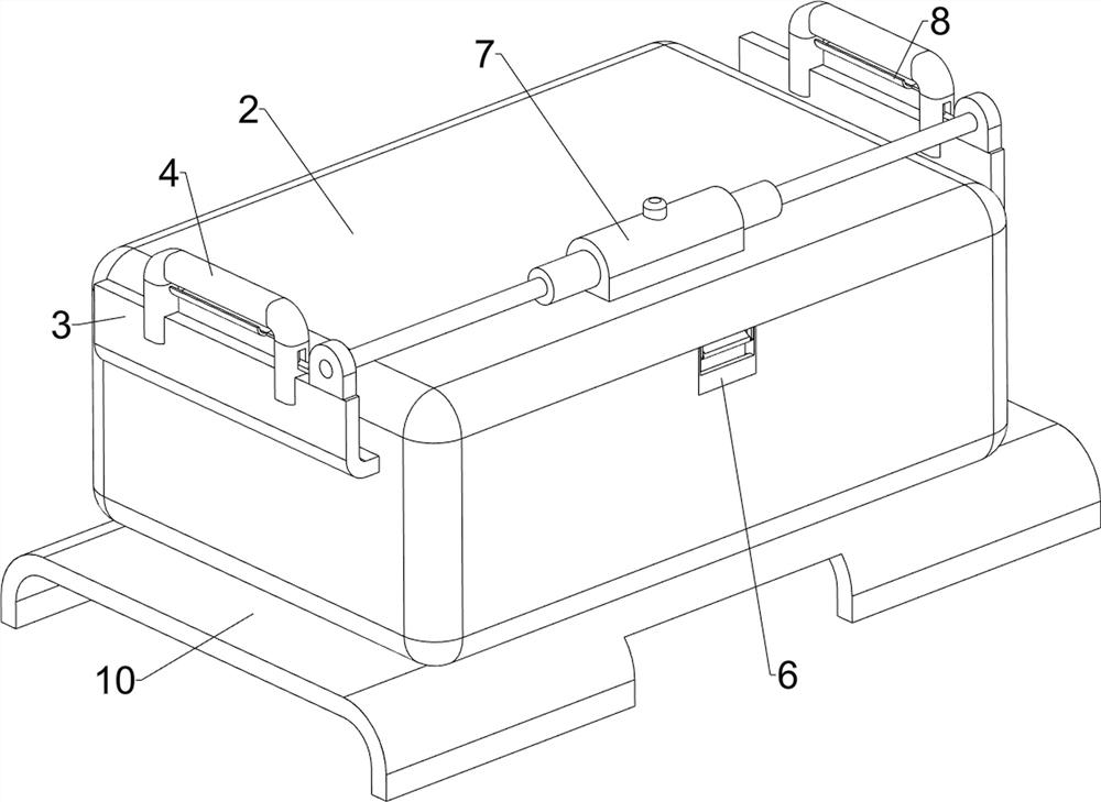
[0032] A new energy vehicle battery carrying case, such as Figure 1-Figure 5 As shown, it includes a casing 1, a cover plate 2, a curved plate 3, a handle 4, a placing mechanism 5 and a locking mechanism 6. The upper rear side of the casing 1 is hingedly provided with a cover plate 2, and the upper parts of the outer casing 1 are fixed on the left and right sides. A curved plate 3 is connected, and a handle 4 is fixed in the middle of the upper part of the curved plate 3. People can move the device to transport the battery through the handle 4. The housing 1 is provided with a placing mechanism 5. The placing mechanism 5 can place the battery. A locking mechanism 6 is provided on the 1, and the locking mechanism 6 can lock the cover plate 2.
[0033] like Figure 2-Figure 4 As shown, the placement mechanism 5 includes a cross plate 51, a movable plate 52, a sliding rod 53, a sliding frame 54, a first buffer spring 55, a groove plate 56, a sliding block 57 and a second buffer...
Embodiment 2
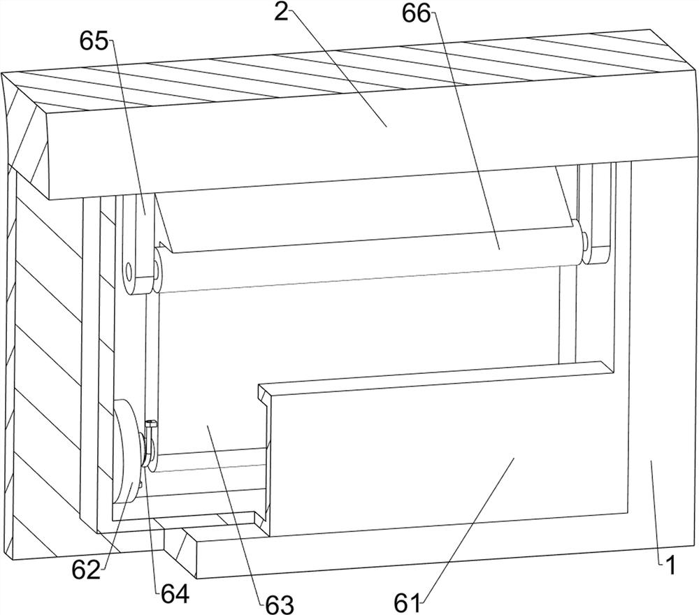
[0037] On the basis of Example 1, as figure 1 , Image 6 and Figure 7 As shown, it also includes a limit mechanism 7 for further limiting the cover plate 2. The limit mechanism 7 includes a fixed seat 71, a limit cylinder 72, a rotating shaft 73, a knob 74, a gear 75, a sliding rod 76, and a rack 77 With the first limit block 78, a fixed seat 71 is fixedly connected to the front and middle side of the top of the cover plate 2, and a limit cylinder 72 is fixed to the left and right sides of the fixed seat 71. The upper middle of the fixed seat 71 is rotatably provided with a knob 74. The knob 74 A rotating shaft 73 is fixedly connected to the bottom, a gear 75 is fixedly connected to the lower part of the rotating shaft 73, a sliding rod 76 is slidably arranged in the limiting cylinder 72, a rack 77 is fixedly connected to the inner end of the sliding rod 76, and a front side of the top of the bent plate 3 is fixedly connected. The first limiting block 78 and the sliding rod...
Embodiment 3
[0042] On the basis of Example 1 and Example 2, as figure 2 and Figure 10 As shown, it also includes a pressing mechanism 9, the pressing mechanism 9 includes a mounting plate 91 and a second limit block 92, the bottom of the bent plate 3 is fixed with a mounting plate 91, and the bottom of the mounting plate 91 is fixed with four second The limit block 92, the second limit block 92 is made of rubber, the second limit block 92 is in contact with the battery, and the second limit block 92 can limit the battery.
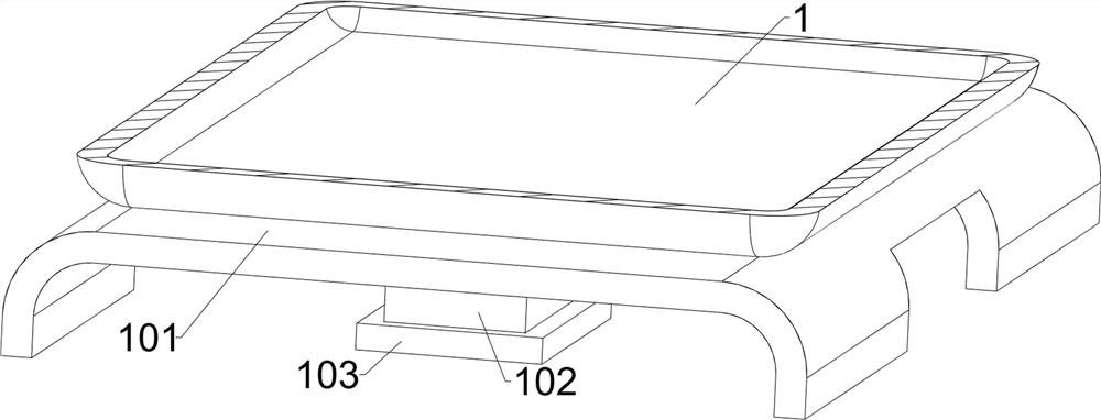
[0043] like figure 1 , figure 2 and Figure 11 Also shown is a stacking mechanism 10. The stacking mechanism 10 includes a base 101, a support block 102 and a rubber sheet 103. A base 101 is fixed to the outer bottom of the housing 1, and a support block 102 is fixed to the bottom of the base 101. When the base 101 is placed When on the handle 4 , the support block 102 can realize support and protection, and the bottom of the support block 102 is fixed with a ru...
PUM
 Abstract
Description
Claims
Application Information
 - R&D
- Intellectual Property
- Life Sciences
- Materials
- Tech Scout
- Unparalleled Data Quality
- Higher Quality Content
- 60% Fewer Hallucinations
Browse by: Latest US Patents, China's latest patents, Technical Efficacy Thesaurus, Application Domain, Technology Topic, Popular Technical Reports.
© 2025 PatSnap. All rights reserved.Legal|Privacy policy|Modern Slavery Act Transparency Statement|Sitemap|About US| Contact US: help@patsnap.com