


Quick Research
Generate reliable direction feasibility study reports for your R&D in just a few steps.

Technical Q&A
Discover and master advanced knowledge NOW. Basics, ideas, possibilities, all at once.

Find Solutions
As an expert in R&D theories, this can generate solutions to your technical problems instantly.

Evaluate Feasibility
Analyze your overall solution with one click, know your potential R&D risks in advance.

Monitor Landscape
Get weekly tech updates, stay abreast of the latest tech innovations and key insights.
Limb restraining device for surgical postoperative nursing
A post-surgical, restraint device technology, which is applied in the fields of restraining the human body, medical science, transportation and packaging, etc., can solve the problems of inconvenient adjustment of the arm clamping force, inability to adjust the restraint by the patient, and the fixation method is not reliable enough, etc. Avoid tearing off the infusion needle, facilitate limb restraint, and secure the effect
- Summary
- Abstract
- Description
- Claims
- Application Information
AI Technical Summary
Benefits of technology
Problems solved by technology
Method used
Image

Examples
Embodiment 1
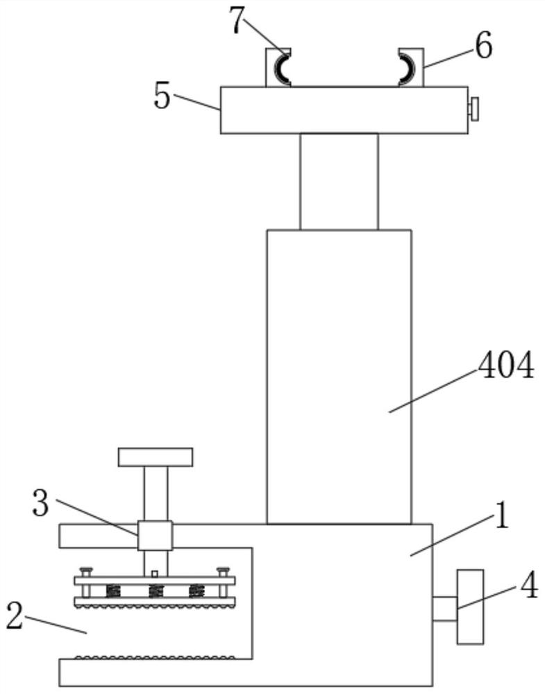
[0027] see Figure 1~4 , a limb restraint device for postoperative care, comprising
[0028] The fixing seat 1 is provided with an installation groove 2 on one side thereof, and a fixing mechanism 3 is fixedly arranged in the installation groove 2, and a through groove is arranged inside the side opposite to the installation groove 2;
[0029] Lifting mechanism 4, which is arranged on the upper side of the fixed seat 1, and its lower side part is arranged in the through groove provided inside the fixed seat 1;
[0030] The clamping mechanism 5 is fixedly installed on the upper end of the lifting mechanism, and two limiting blocks 6 are fixedly installed on its upper side, and the opposite sides of the two limiting blocks 6 are provided with limiting grooves 7 .
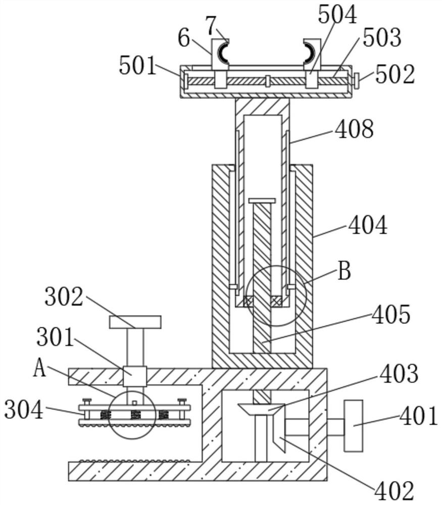
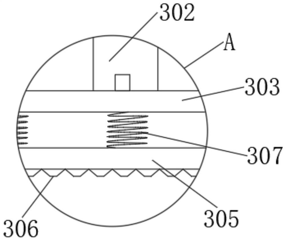
[0031] In the embodiment of the present invention, the fixing mechanism 3 is composed of a nut 301 embedded in the inside of the fixing seat 1 and a pressing block 305, the inside of the nut 301 is threaded with a fa...
Embodiment 2
[0034] see Figure 1~4 , a limb restraint device for postoperative care, comprising
[0035] The fixing seat 1 is provided with an installation groove 2 on one side thereof, and a fixing mechanism 3 is fixedly arranged in the installation groove 2, and a through groove is arranged inside the side opposite to the installation groove 2;
[0036] Lifting mechanism 4, which is arranged on the upper side of the fixed seat 1, and its lower side part is arranged in the through groove provided inside the fixed seat 1;
[0037] The clamping mechanism 5 is fixedly installed on the upper end of the lifting mechanism, and two limiting blocks 6 are fixedly installed on its upper side, and the opposite sides of the two limiting blocks 6 are provided with limiting grooves 7 .
[0038] In the embodiment of the present invention, the lifting mechanism 4 is composed of a handle 401 arranged outside the fixed base 12 and a support rod 404 fixed on the upper surface of the fixed base 1. One end ...
PUM
 Abstract
Description
Claims
Application Information
 - R&D Engineer
- R&D Manager
- IP Professional
- Industry Leading Data Capabilities
- Powerful AI technology
- Patent DNA Extraction
Browse by: Latest US Patents, China's latest patents, Technical Efficacy Thesaurus, Application Domain, Technology Topic, Popular Technical Reports.
© 2024 PatSnap. All rights reserved.Legal|Privacy policy|Modern Slavery Act Transparency Statement|Sitemap|About US| Contact US: help@patsnap.com