Optimization control method for differential pressure and flow at tail end of main pipe network

An optimized control and differential pressure technology, which is applied in the direction of measuring devices, piping systems, and measuring fluid pressure, etc., can solve the problem that the detection structure cannot monitor the pipe pressure at the end of the pipe, cannot adjust the overall pressure of the pipe network in time, and affect the normal operation of the pipe network, etc. problems, to achieve the effect of ensuring reliability, accuracy and stable operation

Pending Publication Date: 2022-05-17
青岛西海岸市政新能源热力有限公司
View PDF0 Cites 0 Cited by
  • Summary
  • Abstract
  • Description
  • Claims
  • Application Information

AI Technical Summary

Problems solved by technology

Therefore, the supply pressure of the pipe network should be determined according to the scale of the pipe network system or the number of points of use. However, the traditional detection structure cannot monitor the pipe pressure at the end of the pipe very well, so that the overall pressure of the pipe network cannot be adjusted in time. Thereby affecting the normal operation of the pipe network, for this reason, the present invention proposes an optimal control method for pressure difference and flow at the end of the main pipe network to solve the above problems

Method used


Image

  • Optimization control method for differential pressure and flow at tail end of main pipe network
  • Optimization control method for differential pressure and flow at tail end of main pipe network
  • Optimization control method for differential pressure and flow at tail end of main pipe network

Examples


Embodiment Construction

[0029] The following will clearly and completely describe the technical solutions in the embodiments of the present invention with reference to the accompanying drawings in the embodiments of the present invention. Obviously, the described embodiments are only some, not all, embodiments of the present invention. Based on the embodiments of the present invention, all other embodiments obtained by persons of ordinary skill in the art without making creative efforts belong to the protection scope of the present invention.

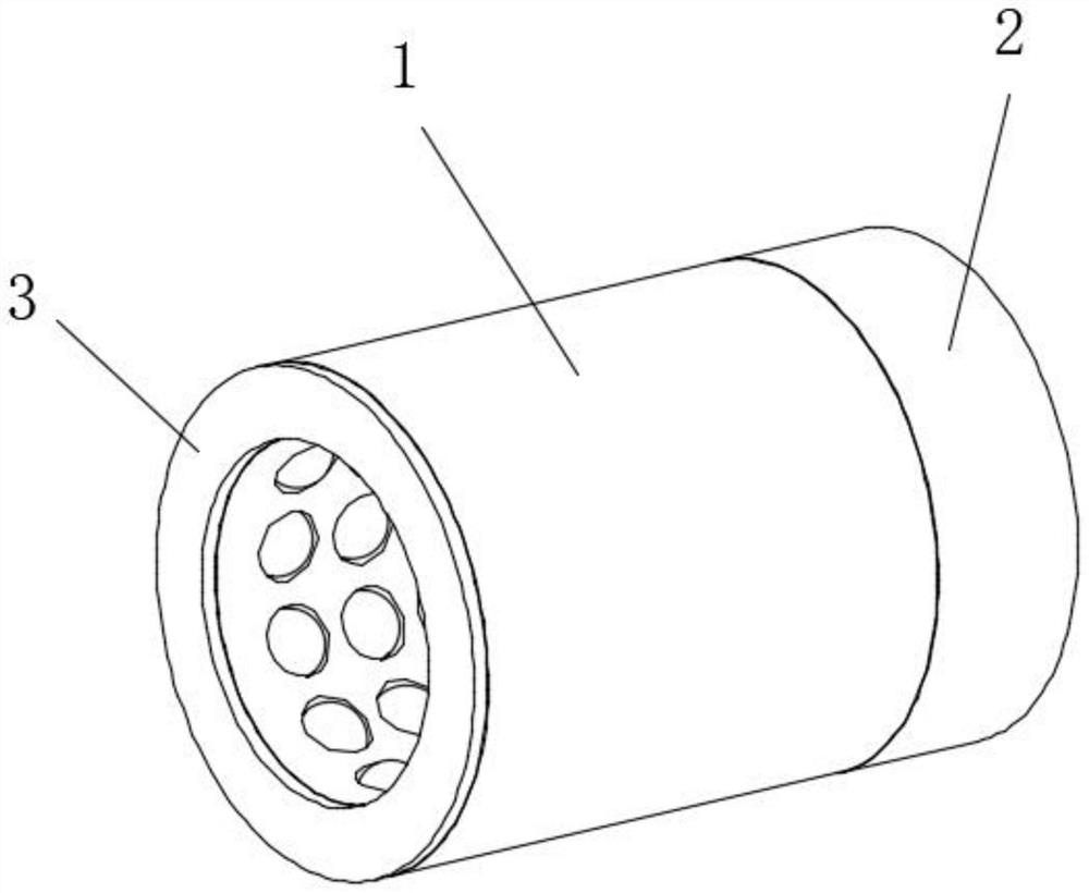
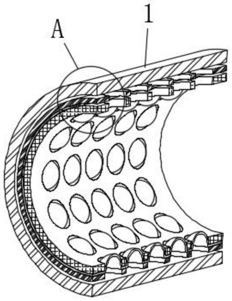
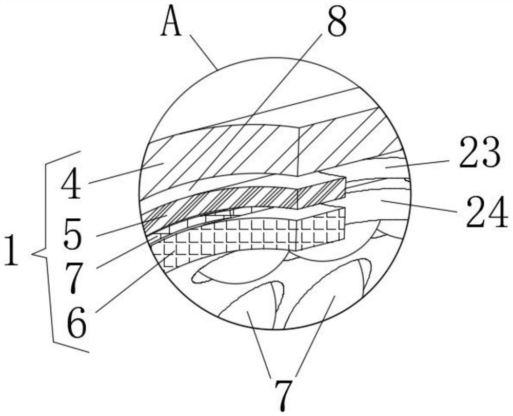
[0030] see Figure 1-7 , the present invention provides a technical solution: a method for optimizing the pressure difference and flow at the end of the main network. The optimal control method for the pressure difference and flow at the end of the main network is to measure the pressure difference at the end of the main network through a detection component. The detection component includes :

[0031] The detection component body 1, the detection component b...


PUM


Abstract

The invention relates to the related technical field of building construction, in particular to an optimal control method for the tail end pressure difference and flow of a main pipe network, and the optimal control method for the tail end pressure difference and flow of the main pipe network comprises the steps that the tail end pressure difference of the main pipe network is measured through a detection assembly, and the detection assembly comprises a detection assembly body, a rear connecting seat and a front connecting seat; the front connecting base is an annular plate, and the inner side face of the front connecting base is fixedly connected with the front side ends of the outer pipe wall, the middle pipe wall and the inner pipe wall. The detection assembly composed of the detection assembly body, the rear connecting seat and the front connecting seat is arranged, and the detection assembly body is composed of the outer pipe wall, the middle pipe wall, the inner pipe wall and the elastic layer, so that the elastic layer is pressed by the pressure in the inner pipe wall, and the change of the air pressure in the air cavity is caused; therefore, the pressure of the tail end of the main pipe network is detected, the overall pipe pressure of the main pipe network is better regulated and controlled, and stable operation of the main pipe network is effectively guaranteed.

Description

technical field [0001] The invention relates to the technical field related to building construction, in particular to an optimal control method for pressure difference and flow at the end of a main network. Background technique [0002] For pipe networks such as water pipes, compressed air, gas, etc., the end pressure refers to the pressure at the rearmost part of the pipe in a pipe network system. If the pipe network system is very large, if the supply pressure at the supply end is too small, when the medium passes through the pipe network, the pressure loss at the end of the medium will cause little or no pressure due to the pressure loss of the medium through the pipe network. Therefore, the supply pressure of the pipe network should be determined according to the scale of the pipe network system or the number of points of use. However, the traditional detection structure cannot monitor the pipe pressure at the end of the pipe very well, so that the overall pressure of t...

Claims


Application Information

Patent Timeline
Patent Type & Authority Applications(China)
IPC IPC(8): F17D5/00G01L19/00
CPCF17D5/00G01L19/00
Inventor 李松刘海鹏赵伟李芳亮褚维礼李娟张丽隋洪越武俊俊
Owner 青岛西海岸市政新能源热力有限公司
Why Eureka
Try Eureka