
Driving structure of electric sliding door

A technology of driving structure and sliding door, which is applied in the direction of power control mechanism, wing leaf control mechanism, door/window accessories, etc. It can solve the problems of damage, detachment from the door frame, and the inability to accurately determine the timing of opening and closing the door, etc., to achieve the goal of improving Stability, the effect of avoiding prolapse

Pending Publication Date: 2022-05-17
湖南省圣宝湘门业有限公司
View PDF0 Cites 0 Cited by
  • Summary
  • Abstract
  • Description
  • Claims
  • Application Information

AI Technical Summary

Problems solved by technology

[0003] The electric sliding door pushes the sliding door by electricity, without manual push, which is more labor-saving. However, because the existing electric sliding door is driven by electric machinery, it is relatively violent when opening and closing, and the main body of the sliding door will collide when opening and closing, seriously Sometimes it will be damaged, or even get out of the door frame, causing harm to nearby personnel, and because the electric machinery cannot accurately determine the timing of opening and closing the door, it often shuts out the person who wants to enter, wasting people's time, and sometimes People or things passing through the sliding door will be collided, and even life-threatening will occur. Therefore, those skilled in the art provide a driving structure for electric sliding doors to solve the problems raised in the above-mentioned background technology

Method used


Image

  • Driving structure of electric sliding door
  • Driving structure of electric sliding door
  • Driving structure of electric sliding door

Examples


Embodiment Construction

[0025] The following will clearly and completely describe the technical solutions in the embodiments of the present invention with reference to the accompanying drawings in the embodiments of the present invention. Obviously, the described embodiments are only some, not all, embodiments of the present invention. Based on the embodiments of the present invention, all other embodiments obtained by persons of ordinary skill in the art without making creative efforts belong to the protection scope of the present invention.

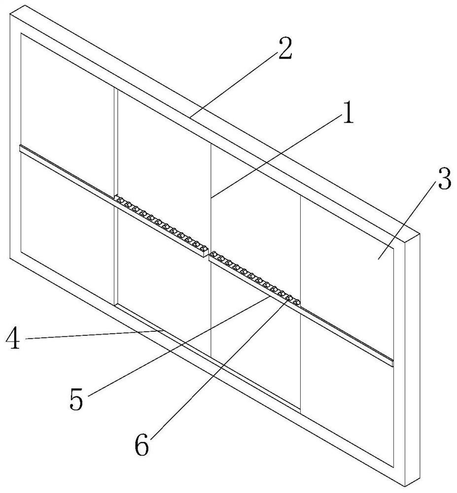
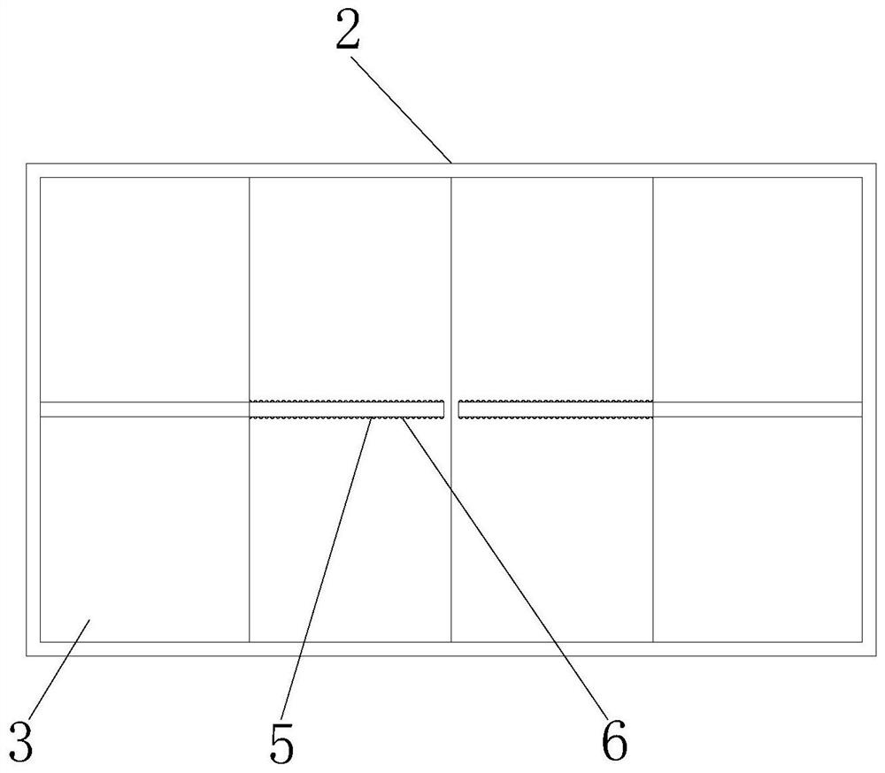
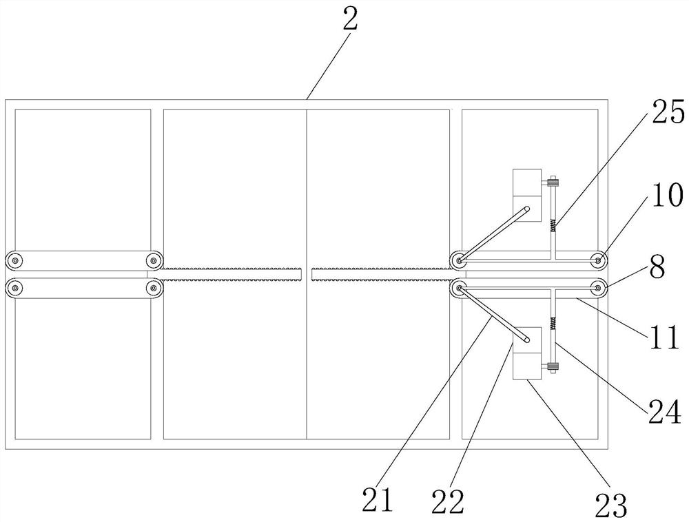
[0026] see Figure 1~6 , in an embodiment of the present invention, a driving structure for an electric sliding door includes a sliding door main body 1, a door frame 2 is movably connected to both sides of the sliding door main body 1, and a fixed baffle 3 is fixedly connected to the inside of the door frame 2, and the sliding door Both sides of the main body 1 are slidingly connected with slide rails 4, both ends of the slide rails 4 are fixedly connected wi...


PUM


Abstract

The invention discloses a driving structure of an electric sliding door in the field of sliding doors, which comprises a sliding door main body, door frames are movably connected to both sides of the sliding door main body, fixed baffles are fixedly connected to the interiors of the door frames, sliding rails are slidably connected to both sides of the sliding door main body, and both ends of the sliding rails are fixedly connected to the fixed baffles. A transverse rod is fixedly connected to the middle of the sliding door body, teeth are fixedly connected to the upper surface and the lower surface of the transverse rod, one side of each tooth is meshed with a gear belt, a rotating cylinder is sleeved with the gear belt, a bearing is fixedly connected to the interior of the rotating cylinder, a rotating shaft is fixedly connected to the interior of the bearing, and a protective box shell is fixedly connected to one side of the bearing. An induction box is fixedly mounted in the middle of the sliding door main body; according to the sliding door, the lifting motor drives the lifting rod to ascend and descend to lift the rotating shaft, so that the rotating cylinder is driven, the gear belt ascends and descends, the contact state of the gear belt and the teeth is switched, the sliding door can be directly stopped during opening and closing, and personnel injury is avoided.

Description

technical field [0001] The invention relates to the field of sliding doors, in particular to a driving structure of an electric sliding door. Background technique [0002] Sliding doors are one of the common doors in life, usually used in wardrobes, bedroom balconies, bathrooms, etc. With the development of modern technology and the diversification of decoration methods and aesthetics, the functions and scope of use of sliding doors are constantly changing. Expansion, from traditional plate materials to fabrics, glass, rattan, and various metal alloys, the materials of sliding doors are constantly being updated, and the size of corresponding sliding doors is also changing, and many large sliding doors have appeared. The scope of application It also extends to other places, such as elevator doors, warehouses, gates of residential areas, etc. After the size and material of sliding doors have changed, it becomes very difficult to manually push and pull sliding doors, so electri...

Claims


Application Information

Patent Timeline
IPC IPC(8): E05F15/635E05F15/73E05F15/42
CPCE05F15/635E05F15/73E05F15/42E05Y2900/132E05Y2800/40
Inventor 王雪平
Owner 湖南省圣宝湘门业有限公司
Learn More