LED dimming circuit, backlight control system and display device

A dimming circuit and dimming technology, applied to electrical components, static indicators, instruments, etc., can solve problems such as the inability to meet the LED display effect and the decline in conversion accuracy

Pending Publication Date: 2022-05-13
BEIJING ESWIN COMPUTING TECH CO LTD
View PDF6 Cites 0 Cited by
  • Summary
  • Abstract
  • Description
  • Claims
  • Application Information

AI Technical Summary

Problems solved by technology

At present, the conversion circuit that converts the input voltage to the output current in the analog circuit, its conversion accuracy will be affected by the manufacturing process of the components in the conversion circuit, which will not meet the display effect of the LED.

Method used


Image

  • LED dimming circuit, backlight control system and display device
  • LED dimming circuit, backlight control system and display device
  • LED dimming circuit, backlight control system and display device

Examples


Embodiment Construction

[0036] In order to facilitate understanding of the present disclosure, the present disclosure will be described more fully below with reference to the related drawings. Preferred embodiments of the present disclosure are shown in the accompanying drawings. However, the present disclosure can be implemented in different forms and is not limited to the embodiments described herein. On the contrary, the purpose of providing these embodiments is to make the understanding of the disclosure content of the present disclosure more thorough and comprehensive.

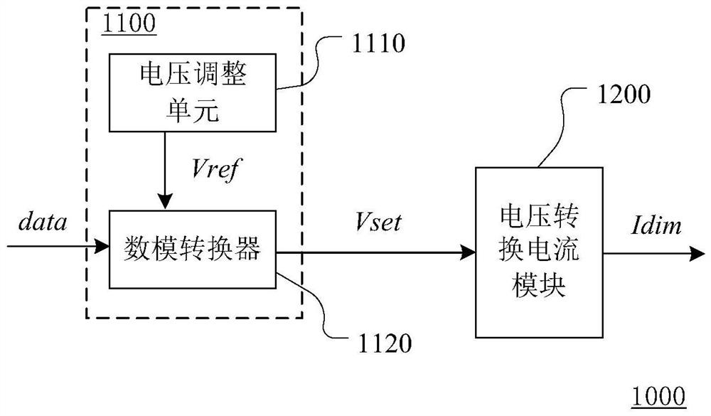
[0037] figure 1 A schematic structural diagram of an LED dimming circuit provided according to an embodiment of the present disclosure is shown. see figure 1 , the LED dimming circuit 1000 includes a voltage generation module 1100 and a voltage conversion current module 1200 . The voltage generation module 1100 is used for providing the dimming voltage Vset. The voltage conversion current module 1200 is connected with the v...


PUM


Abstract

The invention discloses an LED dimming circuit, a backlight control system and a display device thereof, and the LED dimming circuit comprises a voltage generation module which provides dimming voltage; the voltage conversion current module is connected with the voltage adjusting module, converts the dimming voltage into dimming current and outputs the dimming current, and resistance parameters in the voltage generating module and/or the voltage conversion current module are/is adjusted to improve the accuracy of the dimming current. By adjusting the resistance parameters in the voltage generation module and/or the voltage conversion current module, the problem that the precision of the dimming current output by the dimming circuit is reduced due to the influence of a component preparation process is solved.

Description

technical field [0001] The present disclosure relates to the technical field of LED driving, in particular to an LED dimming circuit, a backlight control system and a display device thereof. Background technique [0002] LED (Light Emitting Diode, Light Emitting Diode) has the characteristics of energy saving, environmental protection, high efficiency, long life, etc., and is widely used in lighting, display and other fields. At present, DC dimming mode and / or PWM dimming mode are often used to drive LED display. [0003] In order to obtain a better display visual effect, it is necessary to provide a dimming current with higher precision to the LED. At present, in the conversion circuit that converts the input voltage into the output current in the analog circuit, the conversion accuracy will be reduced due to the influence of the manufacturing process of the components in the conversion circuit, and thus cannot meet the display effect of the LED. Contents of the inventio...

Claims


Application Information

Patent Timeline
Patent Type & Authority Applications(China)
IPC IPC(8): G09G3/34H05B45/30H05B45/37
CPCG09G3/3406H05B45/30H05B45/37
Inventor 徐亮鹏
Owner BEIJING ESWIN COMPUTING TECH CO LTD
Why Eureka
Try Eureka