Adjustable labor-saving valve opening and closing device

A valve device and adjustable technology, applied in the direction of valve device, valve operation/release device, valve details, etc., can solve the problems of easy slipping of the operating valve, cumbersome operation, time-consuming and laborious operation, etc., to avoid frequent replacement and continuous operation Effect

Pending Publication Date: 2022-05-13
陕煤集团榆林化学有限责任公司
View PDF0 Cites 0 Cited by
  • Summary
  • Abstract
  • Description
  • Claims
  • Application Information

AI Technical Summary

Problems solved by technology

At present, the auxiliary device used for valve operation is mainly F-type wrench, but due to the limitation of valve installation position and height, the valve switch operation has problems such as small operating space, time-consuming and labor-intensive operation, and certain safety risks in operation.
In addition, the F-type wrench is cumbersome to operate, and the clamping position needs to be changed frequently, and the valve is easy to slip off when operating, and the F-type wrench concentrates the force on one point of the valve handwheel, and the switch operation will cause great damage to the valve handwheel
For horizontally installed valves, the switch valve can only be operated in the horizontal direction, which brings inconvenience to the operation
[0003] In order to solve the above problems, the traditional method is to use electric valves instead of manual valves, and use electric motors to drive the valves to realize the switching operation of the valves and achieve the purpose of saving time and labor for personnel. However, the structure of electric valves is complex, prone to failure, high cost, and maintenance is relatively expensive. difficulty

Method used


Image

  • Adjustable labor-saving valve opening and closing device
  • Adjustable labor-saving valve opening and closing device
  • Adjustable labor-saving valve opening and closing device

Examples


Embodiment Construction

[0052]In order to make the object, technical solution and advantages of the present invention clearer, the present invention will be further described in detail below in conjunction with the accompanying drawings and embodiments. It should be understood that the specific embodiments described here are only used to explain the present invention, not to limit the present invention.

[0053] Based on the embodiments of the present invention, all other embodiments obtained by persons of ordinary skill in the art without creative efforts fall within the protection scope of the present invention.

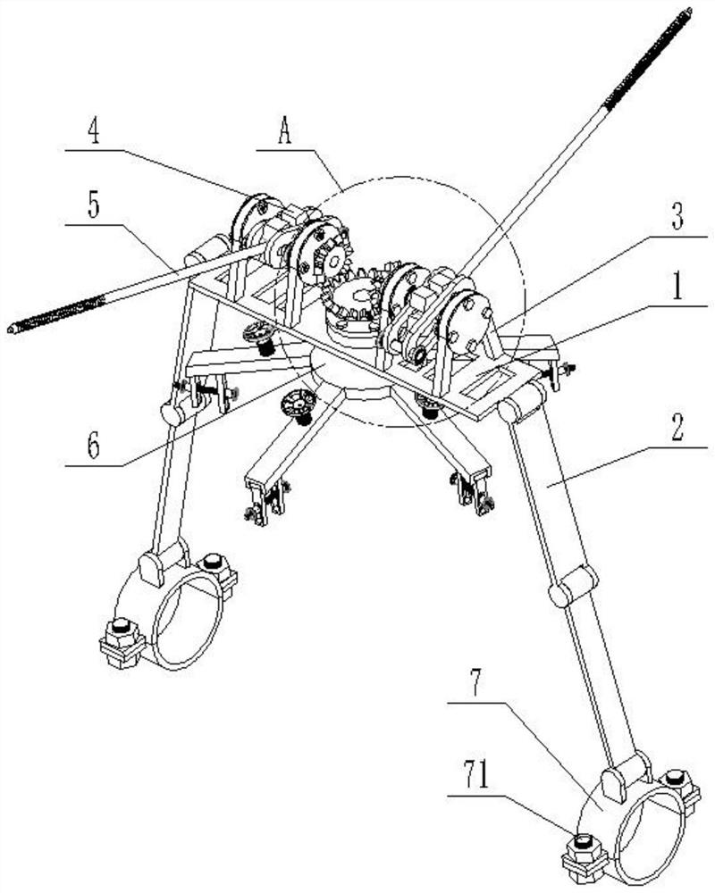
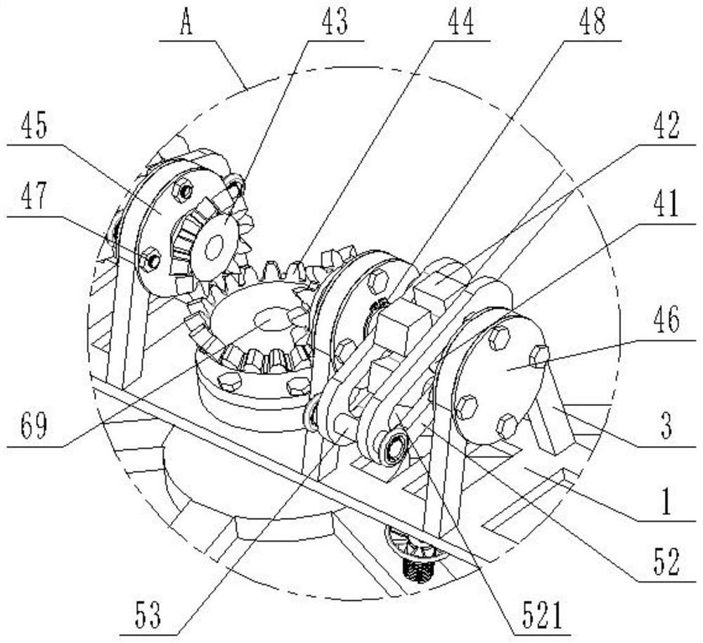
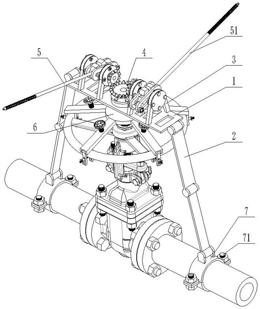
[0054] see Figure 1 to Figure 8 , an adjustable labor-saving switch valve device, including: a main body 1, a hinge rod 2, a mounting bracket 3, a transmission mechanism 4, a handle part 5 and an adjustable chuck 6.

[0055] see Figure 3 to Figure 4 , the two ends of the main body 1 of the body are hinged with hinged rods 2, and are connected to the pipeline through the hinged rods 2;...


PUM


Abstract

The invention provides an adjustable labor-saving valve opening and closing device. The adjustable labor-saving valve opening and closing device comprises a machine body, a transmission mechanism, a grip component and an adjustable chuck. The two ends of the machine body are hinged to hinge supporting rods and connected with the pipeline through the hinge supporting rods. A mounting bracket is arranged on one side of the machine main body; the transmission mechanism comprises a driving shaft, a transmission assembly and a grip fastening wheel, wherein the transmission assembly and the grip fastening wheel are arranged on the driving shaft. The driving shaft is rotationally arranged on the mounting support. The grip part comprises a grip main rod and a sliding adjusting assembly; the sliding adjusting assembly is arranged on the grip fastening wheel in a sleeving mode and connected with the driving shaft in a sliding mode. One end of the adjustable chuck penetrates through the machine body and is connected with the transmission assembly. According to the device, the handle part is rotated, the transmission mechanism is used for driving the adjustable chuck to rotate so as to achieve rotation of the valve hand wheel, operation is more labor-saving, the adjustable chuck can be used for adjusting valve hand wheels of different sizes, the valve hand wheel and the adjustable chuck are fixed, and the slipping problem generated by an F-shaped wrench is avoided.

Description

technical field [0001] The invention relates to the field of valve switch equipment, in particular to an adjustable and labor-saving switch valve device. Background technique [0002] Valve is a kind of equipment widely used in chemical production, which is used to control fluid flow. On-site operators need to frequently switch and adjust some manual valves. At present, the auxiliary device used for valve operation is mainly F-type wrench, but due to the limitation of valve installation position and height, the valve switch operation has problems such as small operating space, time-consuming and labor-intensive operation, and certain safety risks in operation. In addition, the F-type wrench is cumbersome to operate, and the clamping position needs to be changed frequently, and the valve is easy to slip when operating, and the F-type wrench concentrates the force on one point of the valve handwheel, and the switch operation will cause great damage to the valve handwheel. For...

Claims


Application Information

Patent Timeline
IPC IPC(8): F16K31/60F16K31/53
CPCF16K31/60F16K31/53
Inventor 赵相高强刘振虎李斌姜凯李炜
Owner 陕煤集团榆林化学有限责任公司
Why Eureka
Try Eureka