High-speed motor with lubricating function

A high-speed motor and functional technology, applied in lubricating oil containers, lubricating parts, engine lubrication, etc., can solve the problems of single function and small application range, and achieve the effect of easy use

Pending Publication Date: 2021-12-10
熊俊
View PDF5 Cites 0 Cited by
  • Summary
  • Abstract
  • Description
  • Claims
  • Application Information

AI Technical Summary

Problems solved by technology

[0005] In order to overcome the shortcomings of single function and small scope of application, the technical problem to be solved is: to provide a high-speed motor with lubrication function, diversified functional characteristics, and wider application range.

Method used


Image

  • High-speed motor with lubricating function
  • High-speed motor with lubricating function
  • High-speed motor with lubricating function

Examples


Embodiment 1

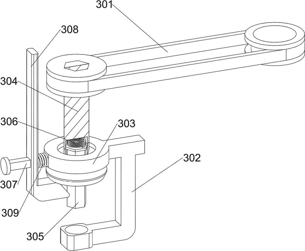
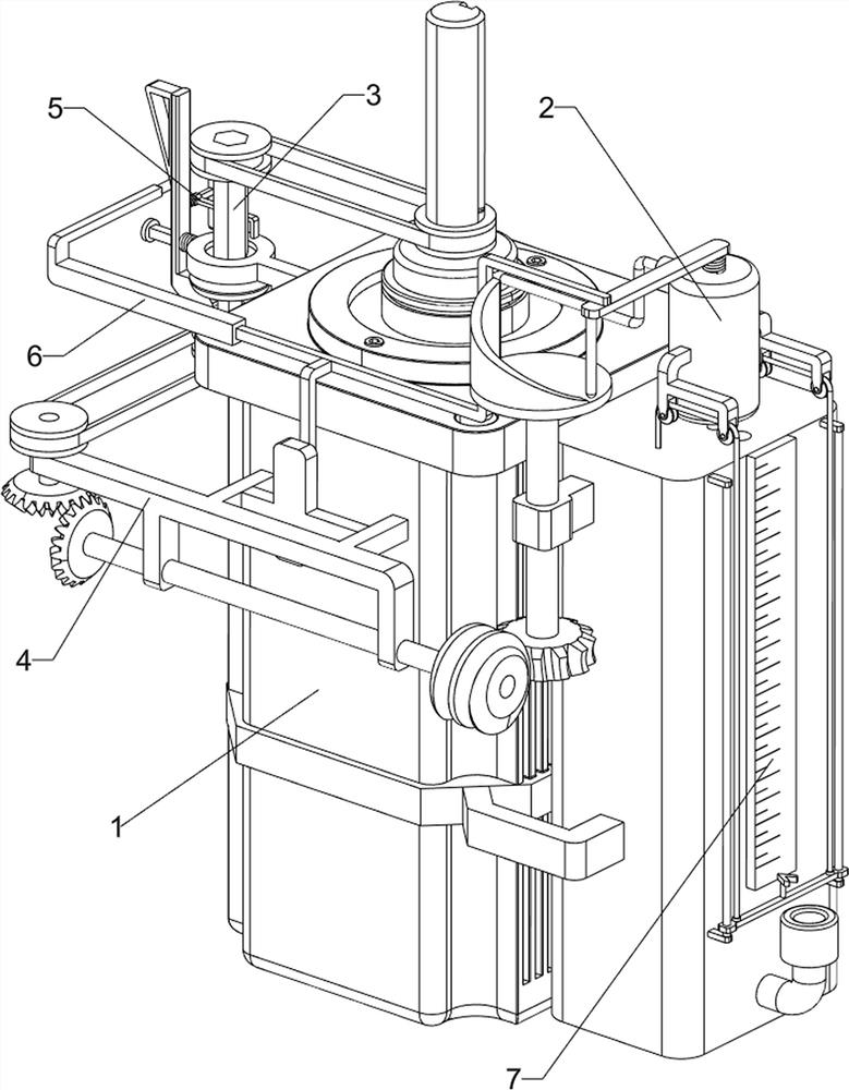
[0079] A high-speed motor with lubrication function, such as figure 1 and figure 2 As shown, it includes a high-speed motor 1, a lubricating component 2, a disengagement component 3 and a driving component 4, a lubricating component 2 is connected between the inner side of the high-speed motor 1, a disengagement component 3 is connected to the output shaft of the high-speed motor 1, and the front of the high-speed motor 1 The drive assembly 4 is connected to the side.

[0080] When the device needs to be used, the user can pour lubricating oil into the lubricating component 2 to achieve the purpose of lubricating the high-speed motor 1. The initial state of the detached component 3 is in a compressed state. Loosen the detached component 3 and detach Component 3 slides down to start the high-speed motor 1. The high-speed motor 1 reverses to drive the detachment component 3 to reverse, and the detachment component 3 reverses to drive the drive component 4 to reverse. When the ...

Embodiment 2

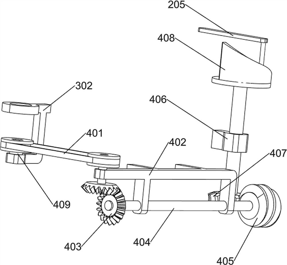
[0082] On the basis of Example 1, such as image 3 As shown, the lubrication assembly 2 includes a storage cylinder 201, a one-way material inlet 202, a piston cylinder 203, a first piston 204, a first push rod 205, a first spring 206, a feed pipe 207, a discharge pipe 208 and Material retaining cover 209, high-speed motor 1 is connected with material storage cylinder 201, and the right side of material storage cylinder 201 is connected with one-way material inlet 202, and the inside of material storage cylinder 201 is connected with feed pipe 207, and feed pipe 207 passes through storage Material cylinder 201, the upper side of feed pipe 207 is connected with piston cylinder 203, and the first piston 204 is slidably connected in the piston cylinder 203, and the first push rod 205 is connected with the first piston 204 upper side, and the first piston 204 and piston cylinder 203 is provided with a first spring 206, the first spring 206 is located on the upper side of the stora...


PUM


Abstract

The invention relates to a high-speed motor, in particular to a high-speed motor with a lubricating function. The invention aims to provide the high-speed motor with the lubrication function, which has the characteristics of lubrication function and diversified functions and is wider in application range. According to the technical scheme, the high-speed motor with the lubricating function comprises a lubricating assembly, a separation assembly and a driving assembly, wherein the lubricating assembly is connected between the inner sides of the high-speed motor; the output shaft of the high-speed motor is connected with the separation assembly; and one side of the high-speed motor is connected with the driving assembly. Through cooperation of a material storage cylinder, a piston cylinder, a first piston and a first push rod, the purpose of feeding lubricating oil to the high-speed motor is achieved.

Description

technical field [0001] The invention relates to a high-speed motor, in particular to a high-speed motor with a lubricating function. Background technique [0002] High-speed motors usually refer to motors whose rotation speed exceeds 10,000r / min. High-speed motors are small in size and can be directly connected to high-speed loads, eliminating the need for traditional mechanical speed-up devices, reducing system noise and improving system transmission efficiency. There are induction motors, permanent magnet motors and switched reluctance motors. [0003] The main characteristics of high-speed motors are high rotor speed, high stator winding current and magnetic flux frequency in iron core, high power density and loss density. These characteristics determine that high-speed motors have key technologies and design methods that are different from normal-speed motors. And the manufacturing difficulty is usually twice that of ordinary speed motors. [0004] The invention develo...

Claims


Application Information

Patent Timeline
Patent Type & Authority Applications(China)
IPC IPC(8): F16N11/08F16N19/00F16N29/00H02K7/10
CPCF16N11/08F16N19/003F16N29/00H02K7/10F16N2210/18F16N2250/18
Inventor 熊俊
Owner 熊俊
Why Eureka
Try Eureka