Winding device with pressing structure for optical fiber manufacturing

A technology of compaction structure and winding device, which is applied in the field of optical fiber manufacturing, can solve the problems of less winding volume of winding rollers, unfavorable optical fiber winding and finishing, and reduced optical fiber winding efficiency, so as to increase winding volume and improve The effect of compactness

Pending Publication Date: 2022-05-13
江苏华晟鑫烨智慧城市科技有限公司
View PDF5 Cites 0 Cited by
  • Summary
  • Abstract
  • Description
  • Claims
  • Application Information

AI Technical Summary

Problems solved by technology

[0002] Optical fiber is a kind of fiber made of glass or plastic. The transmission principle is the total reflection of light. The tiny optical fiber is packaged in a plastic sheath so that it can be bent without breaking. The winding operation is caused by the outer sleeve of the optical fiber and the protective sleeve. During the process, there is a bulge or looseness after the winding is completed, which is not conducive to the winding and arrangement of the whole bundle of optical fibers. At the same time, it will also result in a small amount of winding of a single winding roller, and the winding of the same length of optical fiber requires additional installation. More winding rollers reduce the efficiency of optical fiber winding, so a winding device for optical fiber manufacturing with a compact structure is designed here to solve the above problems

Method used


Image

  • Winding device with pressing structure for optical fiber manufacturing
  • Winding device with pressing structure for optical fiber manufacturing
  • Winding device with pressing structure for optical fiber manufacturing

Examples


Embodiment 1

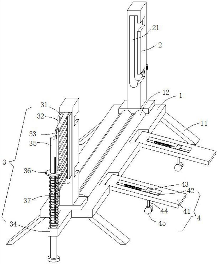
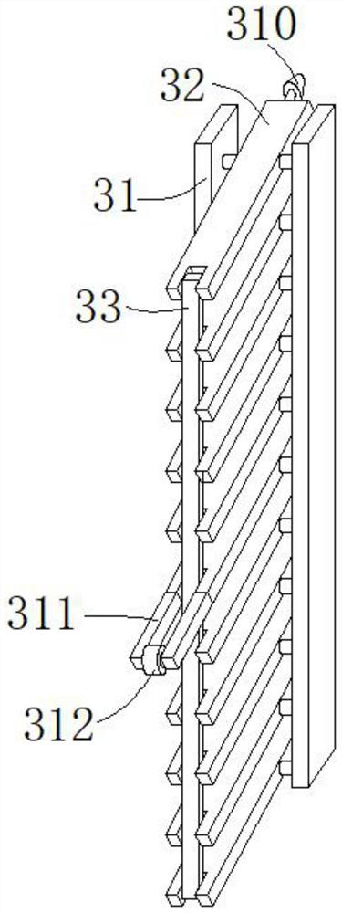
[0032] see figure 1 and image 3 , the present embodiment provides a winding device for optical fiber manufacturing with a pressing structure, including a base 1 and a pressing structure 3, the bottom corner of the base 1 is provided with a leg 11, and the leg 11 is used to The base 1 is stably supported so as to support the winding shaft of the optical fiber to be wound.

[0033] The upper end of the base 1 is vertically provided with two uprights 2 distributed front and back, and the opposite side walls of the two uprights 2 are provided with adjustment holes 21, and the side walls of the two uprights 2 close to each other are provided with feeding gaps distributed up and down. and the feeding gap, the blanking gap is connected with the inner top of the adjustment hole 21, the feeding gap is connected with the inner bottom of the adjustment hole 21, and the end pin shaft of the winding roller is rolled from the feeding gap of the two columns 2 Into the bottom position inside...

Embodiment 2

[0045] see Figure 1-4 , further improvements have been made on the basis of Example 1:

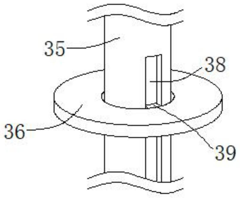
[0046] The compression structure 3 also includes an extension block 34 and an adjustment rod 35, the extension block 34 is fixedly arranged on the front side wall of the base 1, the end of the extension block 34 is rotatably inserted into the adjustment rod 35 through a threaded hole, and the upper end of the adjustment rod 35 Rotate and extend to the top of the extension block 34. The outer wall of the adjustment rod 35 is slidably sleeved with a support plate 36 and a first spring 37. The hinged rod 32 at the position is fixedly provided with two extension rods 311 away from one end of the upright column 2, and the end of the extension rods 311 slides and fits with the upper end surface of the support plate 36, utilizes the extension rods 311 to support the adjusting rod 35, and the first spring 37 The elastic potential energy can push the support plate 36 up in real time along the out...

Embodiment 3

[0053] see figure 1 , Figure 5 and Image 6 , further improvement is made on the basis of embodiment 2:

[0054] During the winding process of the rewinding shaft, it is gradually raised from the innermost end position of the adjustment hole 21. When the pin shaft at the end of the collecting shaft is adjusted to the same height as the feeding gap, it is easy to roll out from the feeding gap, which affects the winding shaft. For normal collection operation, a stopper 5 that can prevent the pin shaft at the end of the rewinding shaft from rolling out of the feed gap is provided inside the feeding gap of the pin shaft at the end of the rewinding shaft, and the pin at the end of the collection shaft is prevented by using the stopper 5. The shaft breaks away from the adjustment hole 21 to ensure that the winding shaft normally winds up the optical fiber.

[0055] The stopper 5 includes a stop rod 51, the stop rod 51 is located inside the feed gap and one end slides through the...


PUM


Abstract

The invention discloses a winding device with a pressing structure for optical fiber manufacturing, and relates to the technical field of optical fiber manufacturing. Optical fibers are pressed down in real time in the winding process through the pressing structure, it is ensured that the phenomenon of protrusion or looseness cannot occur in the winding process, the winding compactness of the optical fibers is improved, and the winding amount of a single winding roller is increased. Comprising a base and a pressing structure, a transmission roller is rotationally embedded in the upper end of the base, two stand columns distributed front and back are vertically arranged at the upper end of the base, the pressing structure comprises two supporting back plates and a plurality of hinge rods, and the two supporting back plates are fixedly installed on the side wall of the side, away from the other stand column, of one stand column; the hinge rods are evenly distributed in the vertical direction at intervals, one ends of the hinge rods extend into the adjusting holes and are rotationally connected with the supporting back plates on the two sides through pin shafts, torsional springs are arranged at the rotating positions of the hinge rods, and connecting rods are hinged between the other ends, away from the supporting back plates, of the hinge rods.

Description

technical field [0001] The invention relates to the technical field of optical fiber manufacturing, in particular to a winding device for optical fiber manufacturing with a pressing structure. Background technique [0002] Optical fiber is a kind of fiber made of glass or plastic. The transmission principle is the total reflection of light. The tiny optical fiber is encapsulated in a plastic sheath so that it can be bent without breaking. The winding operation is caused by the outer sleeve of the optical fiber and the protective sleeve. During the process, there is a bulge or looseness after the winding is completed, which is not conducive to the winding and arrangement of the whole bundle of optical fibers. At the same time, it will also result in a small amount of winding of a single winding roller, and the winding of the same length of optical fiber requires additional installation. Too many winding rollers reduce the efficiency of optical fiber winding, so a winding devi...

Claims


Application Information

Patent Timeline
IPC IPC(8): B65H54/44B65H54/52B65H54/553
CPCB65H54/44B65H54/52B65H54/553B65H2701/32Y02P40/57
Inventor 周建周娥周祥
Owner 江苏华晟鑫烨智慧城市科技有限公司
Why Eureka
Try Eureka