
Multi-layer sliding rail composite motion mechanism and application thereof

A composite motion, slide rail technology, applied in conveyors, transportation and packaging, electrical components, etc., can solve the problem of transporting the product to be tested to the center of the soundproof box, transporting the product to be tested in the soundproof box, increasing the volume of the soundproof box, etc. problem, to improve the effect of acoustic function test, increase the effective movement stroke, and run sensitively.

Active Publication Date: 2022-05-10
P&R MEASUREMENT INC
View PDF5 Cites 0 Cited by
  • Summary
  • Abstract
  • Description
  • Claims
  • Application Information

AI Technical Summary

Problems solved by technology

[0003] At present, due to the size of the inner cavity of the soundproof box, after the test is completed, the product to be tested cannot be transported outside the soundproof box with a single-layer motion slide rail, and the During the test, the product to be tested cannot be transported to the center of the soundproof box. If the inner cavity volume of the soundproof box is increased and the moving slide rail is lengthened, it can meet the requirements of transporting the product to be tested outside the soundproof box or transporting the product to be tested to The demand for the center position of the soundproof box, however, is limited by the structural volume of the soundproof box and the sliding module itself, and it is impossible to meet the requirements of transporting the product to be tested to the center of the soundproof box and transporting the product to be tested at the same time during the test Two-way movement requirements to the outside of the soundproof box; at the same time, increasing the inner cavity volume of the soundproof box and lengthening the motion slide rail will also lead to a sharp increase in manufacturing costs

Method used


Image

  • Multi-layer sliding rail composite motion mechanism and application thereof
  • Multi-layer sliding rail composite motion mechanism and application thereof
  • Multi-layer sliding rail composite motion mechanism and application thereof

Examples


Embodiment 1

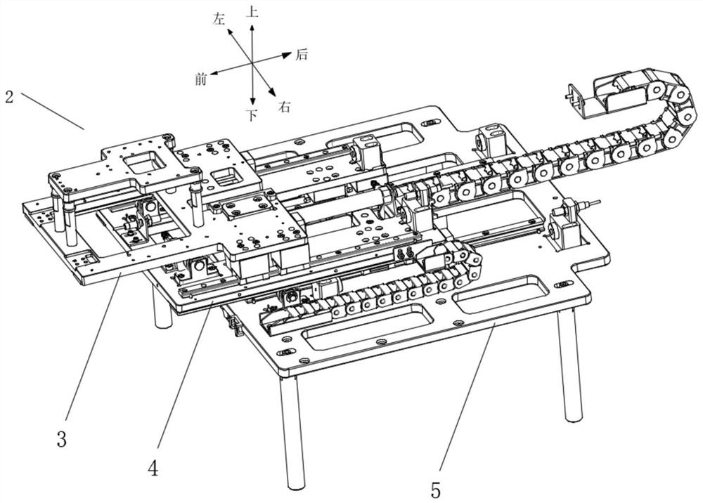
[0034] Such as figure 1 As shown, the present invention provides a multi-layer slide rail compound motion mechanism, the multi-layer slide rail motion mechanism includes a motion module 2, and the motion module 2 includes a carrier module 3, an upper slide rail module 4 and the lower slide module 5; the carrier module 3 is used to place the product to be tested, the carrier module 3 is slidably connected to the upper slide module 4, and the upper slide module 4 Slidingly connected to the lower slide rail module 5.

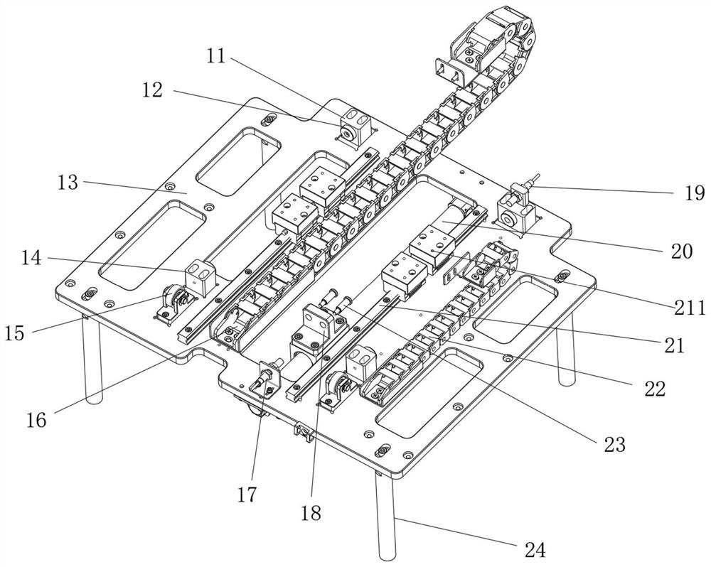
[0035] Such as figure 2 As shown, the lower slide module 5 includes a lower base plate 13 and two lower linear slide rails 21 fixed parallel and symmetrically on the lower base plate 13, and the two lower linear slide rails 21 are fixedly connected to the upper layer through the lower slide block 211. The slide rail module 4; the lower bottom plate 13 is provided with a lower front sensor 17 and a lower rear sensor 19 respectively near the front and rear ends, w...

Embodiment 2

[0044] Such as Figure 6 As shown, the present invention provides a soundproof box 1, the inner cavity of the soundproof box 1 is fixedly installed with the movement module 2 in the first embodiment, and the movement module 2 passes through the lower end of the lower bottom plate 13 of the lower slide rail module 5 The four bottom plate support columns 24 provided are fixedly installed on the inner cavity bottom plate of the soundproof box 1 . Wherein, the soundproof box 1 provides a low-noise environment for acoustic testing and shields noise interference from the external environment; the moving module 2 is used to transport test products into and out of the soundproof box for testing.

[0045] Test process: First, manually place the product to be tested on the carrier base plate 46 of the carrier plate module 3, and accurately locate it by the profiling positioning block set on the carrier base plate 46; then press the start button on the soundproof box 1 button, the upper...

Embodiment 3

[0048] In addition, the present invention also provides a machine loading and unloading transportation device, which also uses any of the above-mentioned multi-layer slide rail compound motion mechanisms to realize product transportation on the production line and complete the product loading and unloading process.

[0049] It needs to be added that the above embodiment is a double-layer slide rail compound motion mechanism. In practical applications, more than two layers of multi-layer slide rail compound motion mechanisms can be adaptively set according to the structure of this embodiment, and its structural principle is similar to , and will not repeat them here.


PUM


Abstract

The invention belongs to the technical field of acoustic testing equipment, and discloses a multi-layer sliding rail composite motion mechanism and application thereof. The multi-layer sliding rail composite motion mechanism comprises a motion module, and the motion module comprises a carrier plate module, an upper-layer sliding rail module and a lower-layer sliding rail module. The carrier plate module is connected to the upper-layer sliding rail module in a sliding mode, and the upper-layer sliding rail module is connected to the lower-layer sliding rail module in a sliding mode. The multi-layer sliding rail composite motion mechanism is placed in an inner cavity of the soundproof box and used for conveying a test product to enter and exit from the soundproof box for testing and can also be used for feeding and discharging conveying of a machine table on a production line. By adopting the multi-layer sliding rail composite motion mechanism, the bidirectional motion position requirements of conveying a test product out of the soundproof box and conveying the test product to the center of the soundproof box can be met at the same time, the volume of an inner cavity of the soundproof box is reduced, the cost is saved, and stable, smooth, sensitive and reliable operation can be ensured.

Description

technical field [0001] The invention belongs to the technical field of acoustic testing equipment, and in particular relates to a compound motion mechanism of multi-layer slide rails and its application. Background technique [0002] As people's requirements for the acoustic function of speaker electronic products are getting higher and higher, the acoustic function test of speaker electronic products usually needs to be carried out in a soundproof box after the production is completed. During the test, the product to be tested needs to be placed in the center of the soundproof box to ensure that the sound is attenuated as uniformly as possible in all directions, so as to avoid the sound reflection that is particularly close to the inner wall of a certain side of the soundproof box and cause interference to the test. . [0003] At present, due to the size of the inner cavity of the soundproof box, after the test is completed, the product to be tested cannot be transported t...

Claims


Application Information

Patent Timeline
Patent Type & Authority Applications(China)
IPC IPC(8): B65G25/06H04R29/00
CPCB65G25/065H04R29/001
Inventor 杨波何伟宇刘力源刘亭伟
Owner P&R MEASUREMENT INC
Learn More