
Counterweight structure of construction machinery

A technology of construction machinery and main counterweight, which is applied to earth movers/shovels, construction, vehicle parts, etc., which can solve problems such as difficult adjustment of counterweight weight, safety accidents, and counterweight jamming, and achieve easy disassembly and assembly , smooth maintenance, and the effect of maintaining weight balance

Pending Publication Date: 2022-05-10
현대두산인프라코어주
View PDF0 Cites 0 Cited by
  • Summary
  • Abstract
  • Description
  • Claims
  • Application Information

AI Technical Summary

Problems solved by technology

[0004] However, the conventional counterweight is fixedly installed on the rear side of the main body of the construction machine, so when a load exceeding the rated load of the construction machine is applied to the work machine, the construction machine may overturn as the rear side of the construction machine rises. accident
[0005] At the construction site, even if the rated load of the construction machinery is known, it is impossible to work while measuring the load of the applied work one by one, which may cause a safety accident
[0006] The possibility of the overturning of the conventional construction machinery is due to the fact that the counterweight mounted on it is a fixed type and it is not easy to adjust the weight of the counterweight.
[0007] In addition, the counterweight of conventional construction machinery is mainly in the shape of a box as a weight body, and is installed in a downward position to provide a sense of stability. As a result, when the construction machine moves backward, the counterweight may often be caught and collide with the surrounding inclined terrain. accident

Method used


Image

  • Counterweight structure of construction machinery
  • Counterweight structure of construction machinery
  • Counterweight structure of construction machinery

Examples


Embodiment Construction

[0049] Preferred embodiments of the counterweight structure of construction machinery of the present invention will be described in detail below with reference to the accompanying drawings.

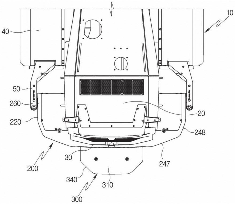
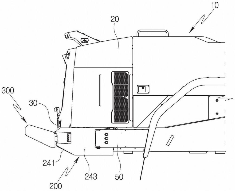
[0050] The counterweight structure 100 of the construction machine of the present invention may be configured to include a main counterweight 200 and a sub counterweight 300 .

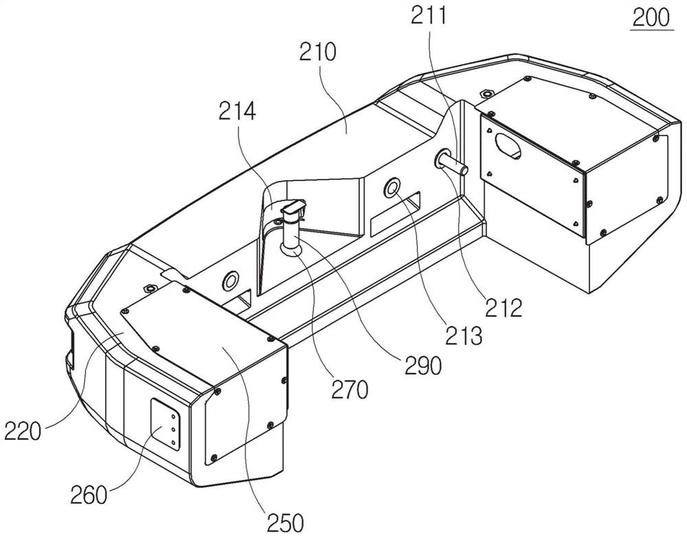
[0051] refer to Figure 2a to Figure 2h , the main counterweight 200 may be configured to include a central portion 210 , a side portion 220 , a battery space portion 250 , a pull-type fender mounting portion 260 and a traction pin mounting portion 270 .

[0052] The central part 210 can be made of metal material, and can be the front surface part 30 (refer to Figure 1a to Figure 1b)part. Such a central portion 210 may be configured to include a first fastening hole 212 , a second fastening hole 213 , a central hole 214 , a central line 215 and a side groove 216 .

[0053] A pair of the first fastening holes 2...


PUM


Abstract

The present invention relates to a counterweight structure of a construction machine, which may be configured to include: a main counterweight including a center portion coupled to a front surface portion of a rear side of a construction machine body, and a side portion coupled to a rear surface portion of the construction machine body; the side parts are bent and arranged on two sides of the central part, and a pull-type mudguard mounting part of a pull-type mudguard which is fastened by a bolt and combined on the rear side of a construction machine body is formed; and a sub-weight including a main body frame coupled to the main weight by a second fitting bolt, and edge tapered portions formed on both sides of the main body frame so as to become narrower in one direction, according to the present invention, it is easy to attach to and detach from a vehicle body of a construction machine, and it is possible to attach to and detach from the vehicle body of the construction machine, and to attach to and detach from the vehicle body of the construction machine, and to attach to and detach from the vehicle body of the construction machine. In addition, due to the fact that the balance weight is composed of a plurality of balance weights, weight balance can be adjusted more effectively, and interference on operation is minimized through rounding machining and inclination machining.

Description

technical field [0001] The present invention relates to a counterweight structure of a construction machine, and in more detail, to a structure that is easy to load and unload on the vehicle body of a construction machine such as a wheel loader, and that can adjust the weight more effectively because it is composed of a plurality of counterweights. The counterweight structure of construction machinery is balanced and minimizes obstruction to work through rounding and inclination processing. Background technique [0002] Generally, construction machines such as wheel loaders, excavators, etc. perform operations of excavating soil, sand, etc. at construction sites or transporting sand, construction materials, etc., and loading or unloading soil, sand, construction materials, etc. on freight vehicles, and It includes a main body including an engine, a work machine mounted on the front side of the main body, and a counter weight as a balance load body for maintaining weight bala...

Claims


Application Information

Patent Timeline
Patent Type & Authority Applications(China)
IPC IPC(8): B62D37/04
CPCB62D37/04E02F9/18E02F9/0858
Inventor 李成均
Owner 현대두산인프라코어주
Learn More