
Assembly method based on PCB surface mounting electronic component device

A technology for electronic components and PCB boards, which is applied in the assembly field of electronic component devices based on the surface mount of PCB boards, can solve the problems of misplacement of electronic components installation, reduction of mounting production efficiency, damage to PCB boards, etc. The effect of quality, efficiency improvement, and yield improvement

Pending Publication Date: 2022-05-06
肖世涛
View PDF0 Cites 2 Cited by
  • Summary
  • Abstract
  • Description
  • Claims
  • Application Information

AI Technical Summary

Problems solved by technology

The existing electronic component assembly device for PCB board is prone to position deviation during the assembly process, which makes the installation of electronic components misplaced and damages the entire PCB board
At the same time, when electronic components are placed, it is necessary to peel off the electronic components on the carrier tape, and then attach the carrier tape to the integrated circuit board (PCB board). This process takes a lot of time and reduces the cost of placement. production efficiency

Method used


Image

  • Assembly method based on PCB surface mounting electronic component device
  • Assembly method based on PCB surface mounting electronic component device
  • Assembly method based on PCB surface mounting electronic component device

Examples


Embodiment Construction

[0039] The present invention will be further explained below in conjunction with the accompanying drawings and specific embodiments. It should be understood that the following specific embodiments are only used to illustrate the present invention and are not intended to limit the scope of the present invention.

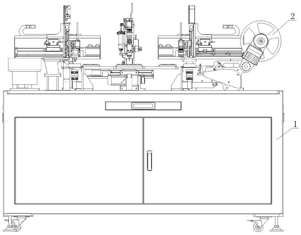
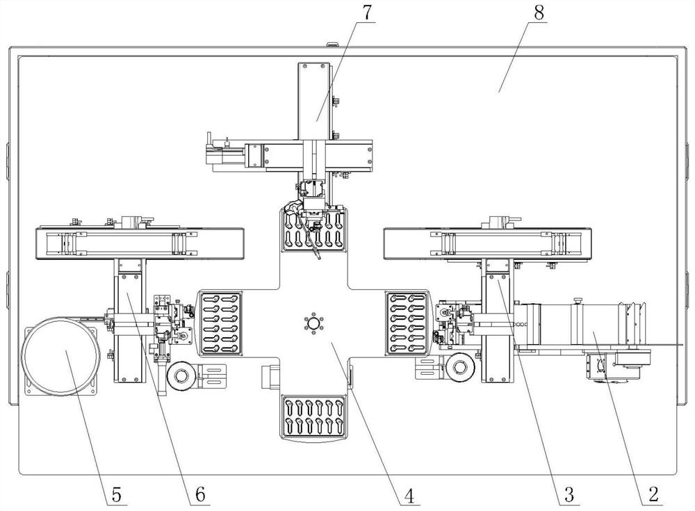
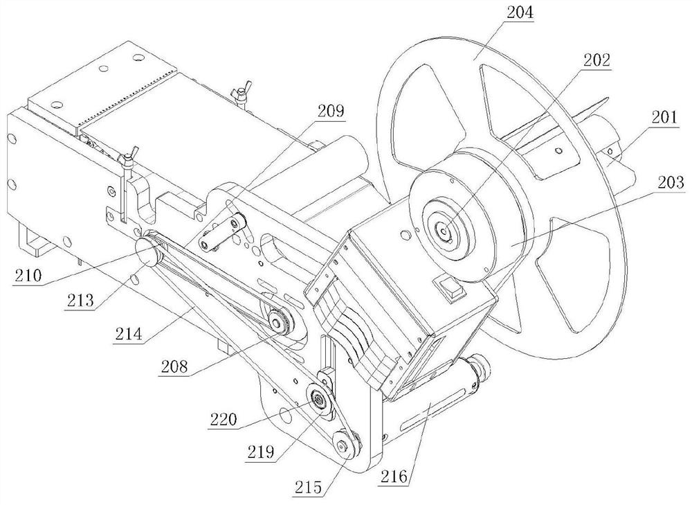
[0040] see figure 1 , 2 As shown, the present invention discloses a surface mount electronic component device for PCB boards, including a frame 1, an electronic component delivery mechanism 2, an electronic component attachment mechanism 3, a turntable rotation mechanism 4, and a PCB board delivery mechanism 5, PCB board handling mechanism 6, dispensing mechanism 7 and PLC controller, the bottom of described frame 1 is fixed with disc leg and roller, and the top of described frame 1 is provided with workbench 8, and described workbench 8 The middle part is provided with a turntable rotation mechanism 4, and the electronic component delivery mechanism 2, the PCB board...


PUM


Abstract

The invention relates to an assembly method based on a surface mounting electronic component device for a PCB (Printed Circuit Board), and mainly solves the problem that an electronic component on a carrier tape needs to be stripped when the existing electronic component is mounted. The surface mounting electronic component device for the PCB comprises a rack, an electronic component conveying mechanism, an electronic component mounting mechanism, a rotary table rotating mechanism, a PCB conveying mechanism, a PCB carrying mechanism, a dispensing mechanism and a PLC, a workbench is arranged at the top of the rack, the rotary table rotating mechanism is arranged in the middle of the workbench, the PCB conveying mechanism is arranged on the rotary table rotating mechanism, and the PCB conveying mechanism is arranged on the rotary table rotating mechanism. According to the technical scheme, the electronic component conveying mechanism, the PCB conveying mechanism and the dispensing mechanism are sequentially arranged around the rotary disc rotating mechanism in a surrounding mode, and the electronic component pasting mechanism is arranged between the rotary disc rotating mechanism and the electronic component conveying mechanism, the problem is well solved, and the automatic assembling machine can be used for assembling electronic components.

Description

technical field [0001] The invention relates to the technical field of PCB boards, in particular to an assembly method for electronic components mounted on the surface of a PCB board. Background technique [0002] The placement machine is also called "mounting machine" and "Surface Mount System". A device that accurately places a device on a PCB pad. Divided into manual and fully automatic two. The automatic placement machine is a device used to realize high-speed and high-precision automatic placement of components. It is the most critical and complex equipment in the entire SMT production. The placement machine is the main equipment in the SMT production line. The placement machine has developed from an early low-speed mechanical placement machine to a high-speed optical centering placement machine, and has developed into a multi-functional, flexible connection modularization. When assembling electronic components in the prior art, machines are generally used for assemb...

Claims


Application Information

Patent Timeline
Patent Type & Authority Applications(China)
IPC IPC(8): H05K13/02H05K13/00H05K13/04H05K13/08
CPCH05K13/021H05K13/0061H05K13/0469H05K13/0812
Inventor 肖世涛
Owner 肖世涛
Learn More