Anti-vibration replacement pin for lens

A lens, anti-vibration technology, used in instruments, installations, optics, etc., can solve the problem that telephoto lenses cannot eliminate resonance.

Pending Publication Date: 2022-05-06
朴龙吉
View PDF0 Cites 0 Cited by
  • Summary
  • Abstract
  • Description
  • Claims
  • Application Information

AI Technical Summary

Problems solved by technology

[0002] The lens anti-vibration replacement foot is an accessory for installing and fixing the lens. In the current existing technology, due to design defects, the combination and installation of the telephoto lens from the tripod cannot eliminate resonance. Therefore, a lens anti-vibration replacement foot is invented.

Method used


Image

  • Anti-vibration replacement pin for lens
  • Anti-vibration replacement pin for lens
  • Anti-vibration replacement pin for lens

Examples


Embodiment Construction

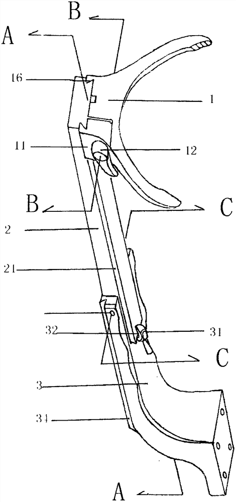
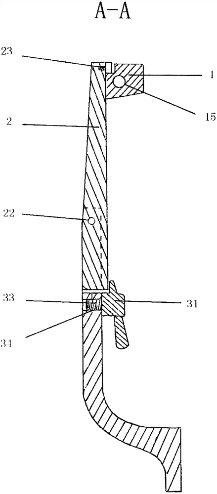
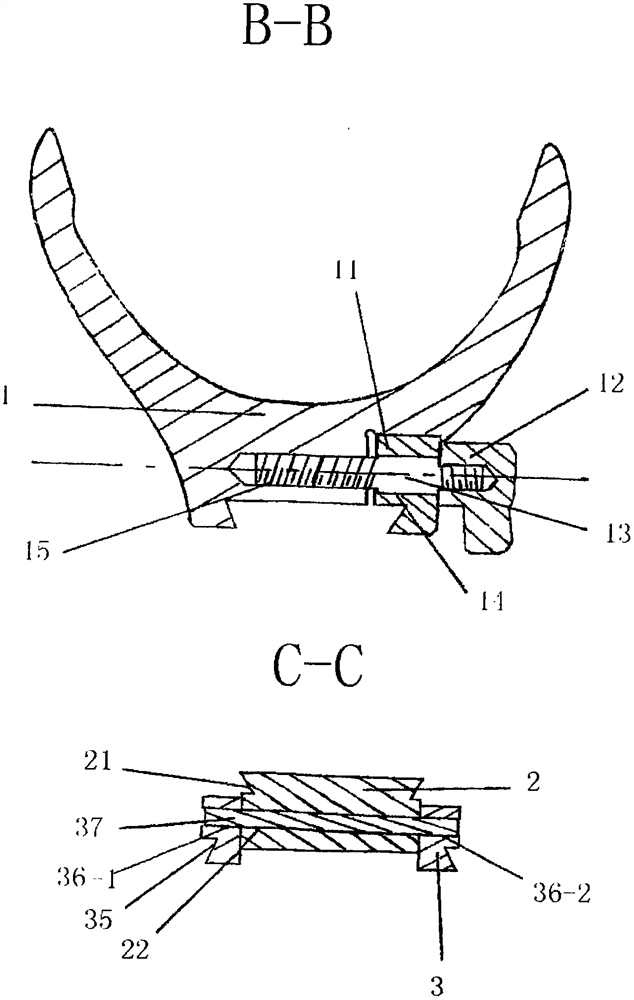
[0010] The following will combine figure 1 , figure 2 , image 3 , the accompanying drawings illustrate the present invention in detail.

[0011] Lens anti-vibration replacement foot 3, including replacement foot 3, extension plate 2, support frame 1, plate buckle 31, extension plate dovetail groove 21, extension plate side hole 22, pin 37, replacement foot left hole 36-1, replacement foot Right side hole 36-2, dovetail groove 35, limit screw 23; the replacement foot 3 is connected to the middle part of the extension board 2, wherein the pin 37 passes through the left side hole 36-1 of the replacement foot, the side hole 22 of the extension board and the right side of the replacement foot The hole 36-2 is connected, the hole 36-1 on the left side of the replacement foot, the side hole 22 of the extension plate, and the right hole 36-2 of the replacement foot are mutually matched and adjacent; the support frame 1 is arranged on the upper part of the extension plate 2, includ...


PUM


Abstract

The lens anti-vibration replacement foot comprises a replacement foot body, an extension plate, a supporting frame and a plate buckle. The replacement foot is connected with the extension plate, the extension plate is in contact connection with the supporting frame, the replacement foot is connected with the middle of the extension plate, the pin is connected with the replacement foot right side hole through the replacement foot left side hole and the extension plate side hole, the plate buckle is arranged on the upper portion of the replacement foot and can rotate by 90 degrees, and the extension plate and the replacement foot are horizontally locked by 180 degrees when the plate buckle is pushed to rotate by 90 degrees. The plate buckle is pulled and rotated by 90 degrees, the extension plate and the replacement foot are opened by 15 degrees, the supporting frame slides back and forth on the extension plate, the replacement foot is used for limiting and controlling the lens to be stable, vibration and resonance of the lens are thoroughly eliminated, and therefore the original anti-shake function of the lens is restored.

Description

technical field [0001] The invention relates to a photographic auxiliary accessory, in particular to a lens anti-vibration replacement foot. Background technique [0002] The lens anti-vibration replacement foot is to install and fix the lens support accessories. In the current prior art, due to design defects, the combination and installation of the telephoto lens from the tripod cannot eliminate the resonance. Therefore, a lens anti-vibration replacement foot was invented. Contents of the invention [0003] The anti-vibration replacement foot for the lens of the present invention completely solves the vibration and resonance of the lens, and controls the stability of the lens to the limit. In order to achieve the above purpose, the present invention adopts the following technical solutions. [0004] Lens anti-vibration replacement feet, including replacement feet, extension boards, support frames, plate buckles, extension board dovetail slots, extension board side holes,...

Claims


Application Information

Patent Timeline
Patent Type & Authority Applications(China)
IPC IPC(8): G02B7/02G02B27/64
CPCG02B7/022G02B27/646
Inventor 朴龙吉
Owner 朴龙吉
Why Eureka
Try Eureka