Combined multifunctional illuminating lamp for aviation illumination
A lighting and combined technology, applied in the field of lighting, can solve the problems of single function of lighting, inconvenient disassembly and assembly of lighting, and inability to meet maintenance operations, etc.
- Summary
- Abstract
- Description
- Claims
- Application Information
AI Technical Summary
Problems solved by technology
Method used
Image
Examples
Embodiment 1
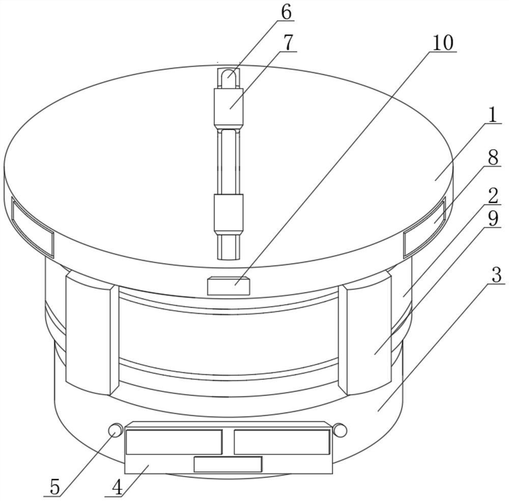
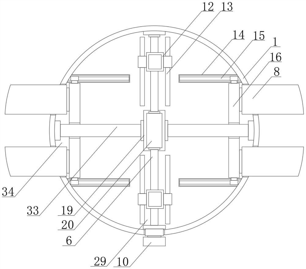
[0026] see Figure 1-5 , the present embodiment provides a combined multifunctional lighting lamp for aviation lighting, including a mounting plate 1, a worm wheel 19 is provided inside the mounting plate 1, and a worm 20 is meshed and connected to one side of the worm wheel 19, and the worm wheel 19 and the worm 20 are connected to each other. Both sides are provided with a fixing mechanism 34, and the fixing mechanism 34 includes two second moving plates 16, and the opposite ends of the two second moving plates 16 are symmetrically fixedly connected with two second inserting blocks 8, a worm wheel 19 and a worm 20 The top and the bottom of the mounting plate 1 are provided with a moving mechanism 29, the moving mechanism 29 includes two threaded rods 6, the two sides of the two threaded rods 6 are fixedly connected with a moving limit rod 13, and the bottom of the mounting plate 1 is fixedly connected with a fireproof shell 2 The interior of the fireproof shell 2 is provided...
Embodiment 2
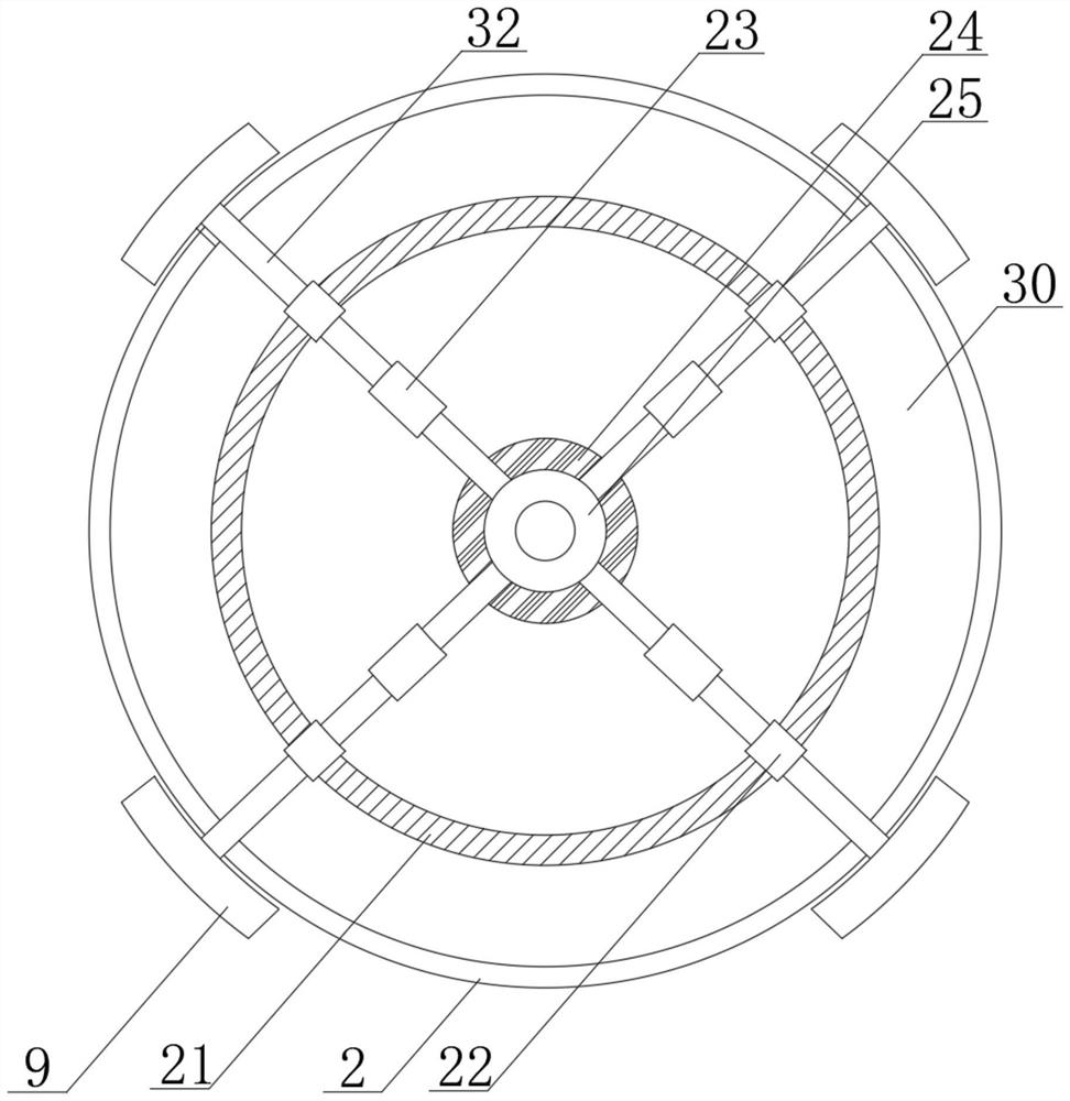
[0036] see image 3 , further improvements have been made on the basis of Example 1:
[0037] In order to realize the effect of fire prevention, a rotating motor 24 is installed on the bottom of the rotating disk 25, and one end of each connecting rod 32 away from the rotating disk 25 is fixedly connected with a sliding block 22, and the other end of the sliding block 22 runs through the fireproof shell 2 and is fixedly connected with a Spray block 9.
[0038] The bottom end surface in the fireproof shell 2 is fixedly connected with a circular limiting groove 21, and the bottom end of the sliding block 22 is slidably connected in the circular limiting groove 21, and each connecting rod 32 is fixedly connected with a water pump 23, and the water pump 23 The surface is connected to the water outlet system through water pipes.
[0039] In this embodiment, since the smoke sensor is installed on the sprinkler block 9, the effect of fire monitoring can be played at this time. When...
Embodiment 3
[0041] see Figure 4 and 5 , further improvements have been made on the basis of Example 1:
[0042] The locking mechanism 31 includes a partition 18 fixedly connected in the insertion box 26, and springs 17 are fixedly connected to both ends of the partition 18, and the end of the spring 17 away from the partition 18 is fixedly connected to the first moving plate 11, and the first moving The end of the plate 11 away from the spring 17 is fixedly connected to the limit block 27, and the end of the limit block 27 away from the partition plate 18 is an inclined plane.
[0043] The bottom ends of the two first moving plates 11 are fixedly connected with a fixing piece, and the other end of the fixing piece runs through the lighting lamp 3, and two pull blocks 28 are arranged symmetrically on one side of the lighting lamp 3, and the two pull blocks 28 are close to the lighting One end of the lamp 3 is fixedly connected with a connecting block, and the other end of the connecting...
PUM
 Abstract
Description
Claims
Application Information
 - R&D
- Intellectual Property
- Life Sciences
- Materials
- Tech Scout
- Unparalleled Data Quality
- Higher Quality Content
- 60% Fewer Hallucinations
Browse by: Latest US Patents, China's latest patents, Technical Efficacy Thesaurus, Application Domain, Technology Topic, Popular Technical Reports.
© 2025 PatSnap. All rights reserved.Legal|Privacy policy|Modern Slavery Act Transparency Statement|Sitemap|About US| Contact US: help@patsnap.com


