
Spiral underground packing tool

A helical and helical sealing technology, which is applied in sealing/isolation, wellbore/well parts, earthwork drilling and production, etc. It can solve the problems of uneven deployment and anchoring, reduced pressure bearing capacity of downhole isolation tools, and isolation failure, etc. problems, to achieve the effect of improving the anti-pre-set sealing effect, improving the sealing pressure bearing effect, and ensuring the uniformity

Pending Publication Date: 2022-05-06
VERTECHS PETROLEUM TECH INNOVATION & EQUIP MFG CO LTD
View PDF12 Cites 0 Cited by
  • Summary
  • Abstract
  • Description
  • Claims
  • Application Information

AI Technical Summary

Problems solved by technology

[0002] When the downhole isolation tool completes the setting process downhole, the slips of the downhole isolation tool will be expanded and squeezed to the inner wall of the wellbore. During the expansion process of the slips, due to the uneven force on the slips in the radial direction, the slips will be deployed first at the place where the force is greater, and the force on the slips at the first deployment will continue to increase As a result, the slips in this place are relatively large, and the slips in other places are relatively small, causing the slips to be deployed and anchored unevenly on the inner wall of the wellbore, which reduces the pressure bearing capacity of the downhole isolation tool in the radial direction and affects the downhole isolation tool. If the sealing and pressure bearing effect is not enough, further center pipe will come out, resulting in failure of containment

Method used


Image

  • Spiral underground packing tool
  • Spiral underground packing tool
  • Spiral underground packing tool

Examples


Embodiment Construction

[0054] The principles and features of the present invention are described below in conjunction with the accompanying drawings, and the examples given are only used to explain the present invention, and are not intended to limit the scope of the present invention.

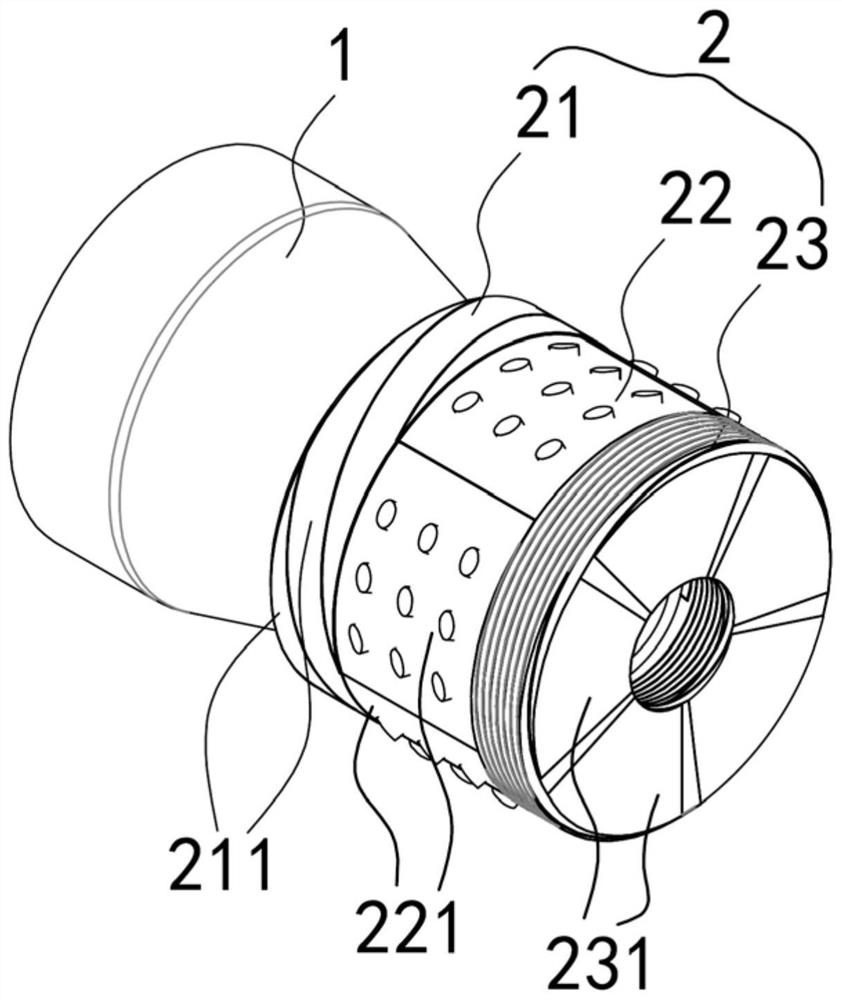
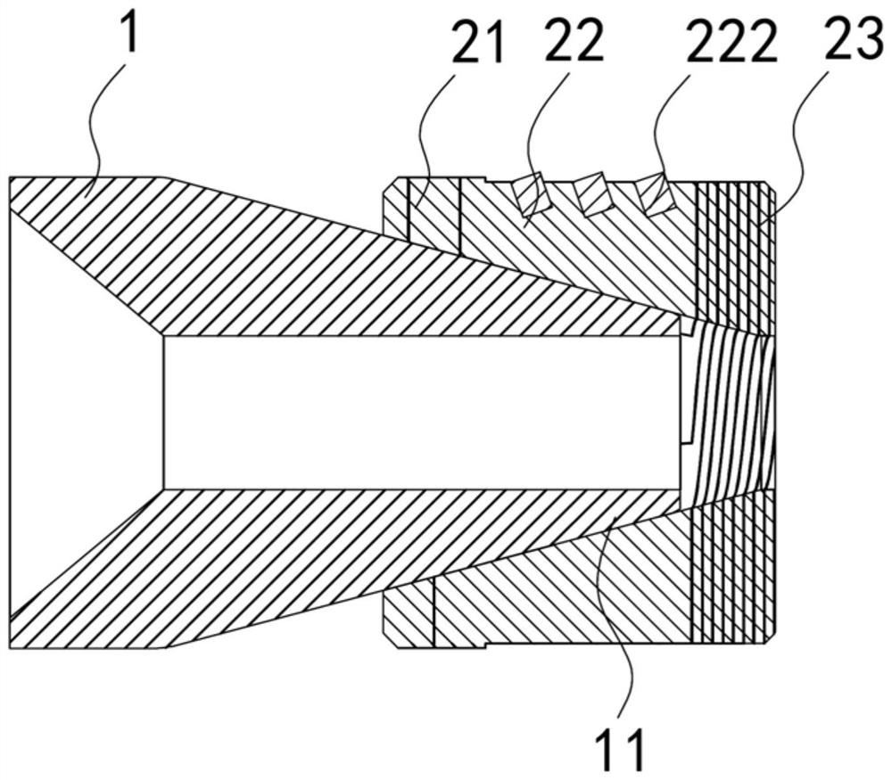
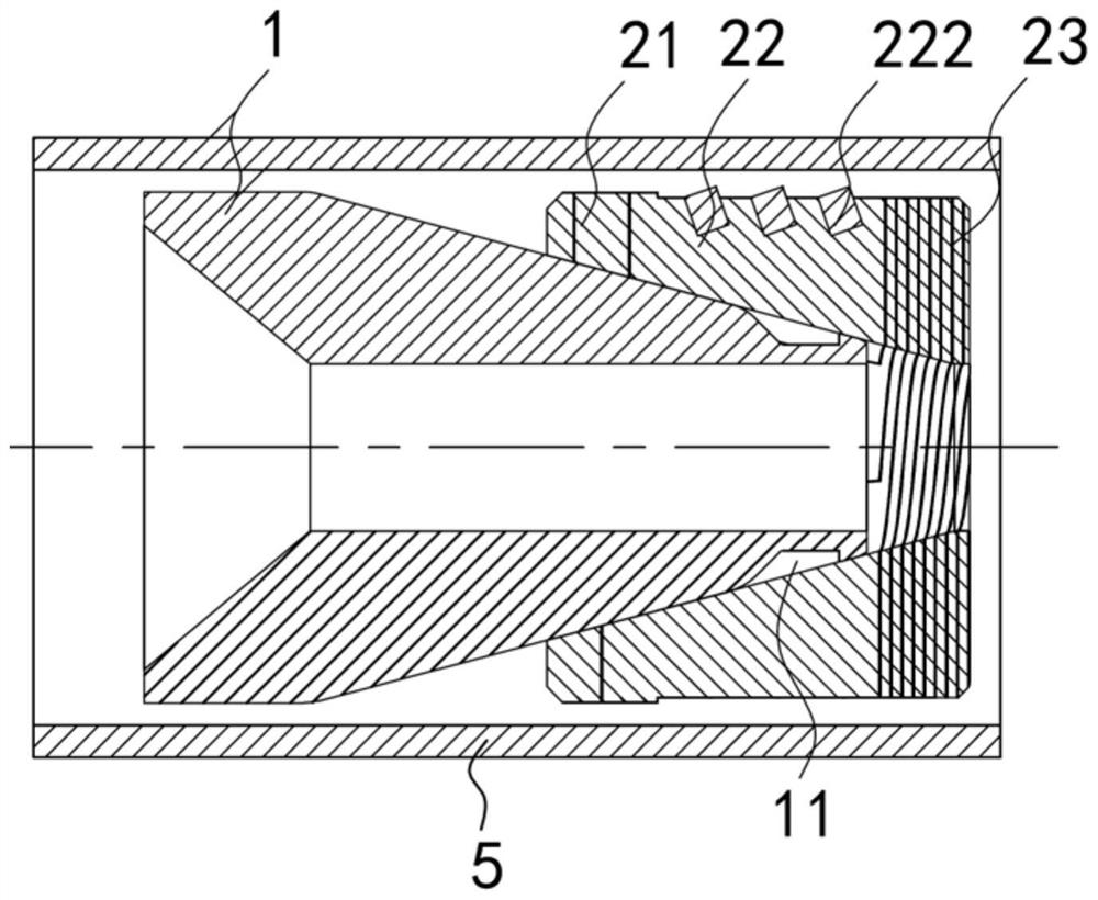
[0055] For a structural schematic diagram of Embodiment 1 of the spiral downhole isolation tool of the present invention, see Figure 1 to Figure 4 .

[0056] A spiral downhole isolation tool, comprising: a center pipe 1 with a tapered outer surface, and the center pipe 1 has an axial through hole.

[0057] An anchor sealing structure 2, the anchor sealing structure 2 is matched and sleeved on the outer surface of the central pipe 1, the anchor sealing structure 2 has a first sealing section 21 and an anchoring section 22, the first sealing section 21 is located on the center pipe 1 At the big end, the anchoring section 22 includes a plurality of slips 221, the first sealing section 21 includes a plurality of first...


PUM


Abstract

The invention relates to the field of petroleum underground construction, in particular to a spiral underground packing tool which comprises a central pipe with a conical outer surface, an anchoring sealing structure is arranged on the outer surface of the central pipe in a matched and sleeved mode, the anchoring sealing structure is provided with a first sealing section and an anchoring section, and the anchoring section comprises a plurality of slips. The plurality of slips and the plurality of first spiral sealing rings are in one-to-one correspondence and respectively form an integrated structure; a locking structure matched with the locking main body is arranged on the central pipe, the locking main body comprises a plurality of spiral locking rings, and the plurality of slips and the plurality of spiral locking rings are in one-to-one correspondence and respectively form an integral structure. The multiple slips are evenly unfolded in the radial direction, the slips are evenly distributed in the circumferential direction, the slips are evenly anchored on the inner wall of a whole shaft, the uniformity of the pressure bearing capacity of an underground packing tool in the radial direction is guaranteed, and the sealing pressure bearing effect is improved. In addition, the spiral locking ring is matched with the locking structure in a locking mode, so that the anchoring sealing structure is prevented from falling off from the central pipe.

Description

technical field [0001] The invention relates to the field of petroleum downhole construction, in particular to a spiral downhole isolation tool. Background technique [0002] When the downhole isolation tool completes the setting process downhole, the slips of the downhole isolation tool will be expanded and squeezed to the inner wall of the wellbore. The slips are generally composed of multiple slips. During the expansion process of the slips, due to the The force received by the shoe in the radial direction is not uniform, and the slips will be deployed first at the place where the force is greater. Because the force on the slips at the place where the force is first deployed will continue to increase, the slips at this location will be larger, and the slips at other places will be deployed. If the slips are too small, the anchoring of the slips on the inner wall of the wellbore will be uneven, which will reduce the pressure bearing capacity of the downhole isolation tool ...

Claims


Application Information

Patent Timeline
Patent Type & Authority Applications(China)
IPC IPC(8): E21B33/12E21B23/06
CPCE21B33/1208E21B23/06E21B33/1292
Inventor 郑威曾琦军邱成松王锦路
Owner VERTECHS PETROLEUM TECH INNOVATION & EQUIP MFG CO LTD
Learn More