Multi-working-face industrial angle iron

A multi-face, angle iron technology

Pending Publication Date: 2022-05-03
吴祥年
View PDF0 Cites 0 Cited by
  • Summary
  • Abstract
  • Description
  • Claims
  • Application Information

AI Technical Summary

Problems solved by technology

[0004] In order to make up for the deficiencies of the existing technology and solve the problem that the angle iron is difficult to fix some objects that do not have a vertical surface, the invention proposes a multi-face industrial angle iron

Method used


Image

  • Multi-working-face industrial angle iron
  • Multi-working-face industrial angle iron
  • Multi-working-face industrial angle iron

Examples


Embodiment approach

[0054] As an embodiment of the present invention, the connecting unit includes:

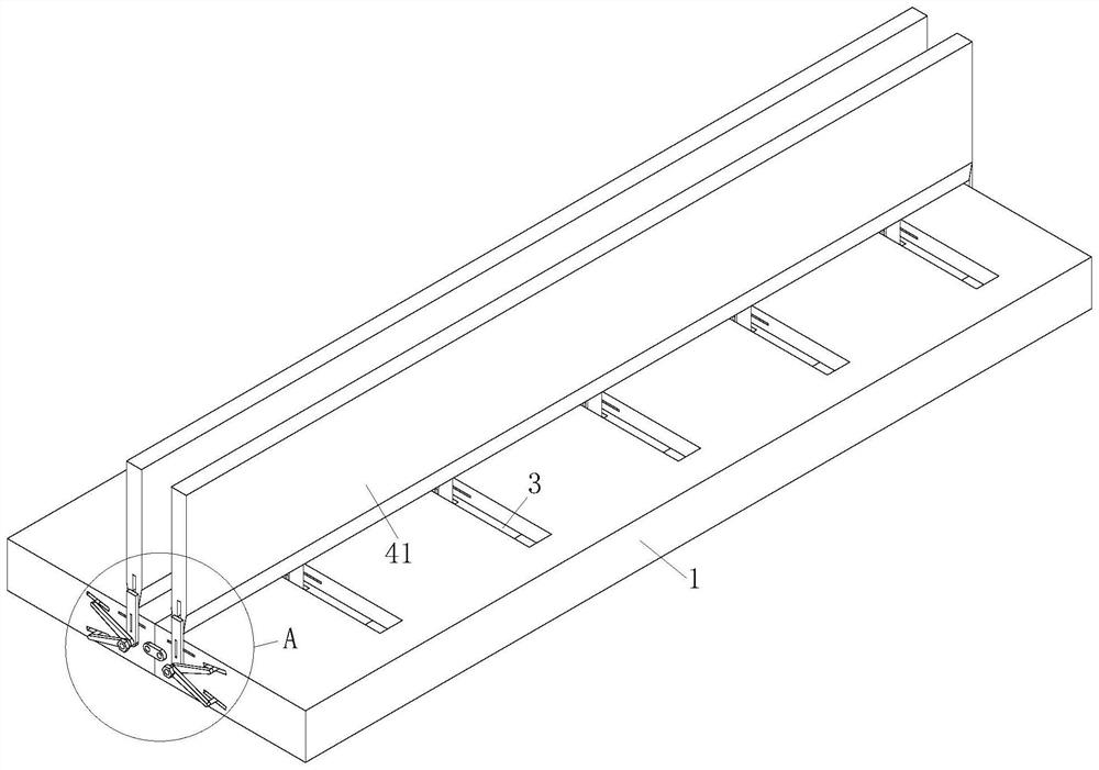
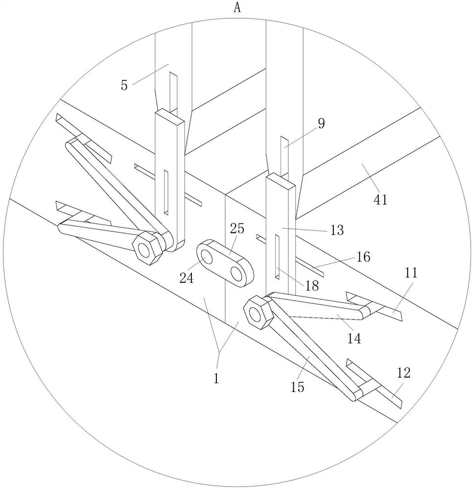
[0055] Rotation groove 6, said rotation groove 6 vertically penetrates on said horizontal plate 42, and said rotation groove 6 is located on the opposite end of two said horizontal plates 42;

[0056] Rotating rod 7, the rotating rod 7 is fixed on the lower end of the upper plate 41, and the lower end of the rotating rod 7 extends into the inside of the rotating groove 6 through the chute 3;

[0057] Connecting rod 8, the connecting rod 8 is arranged on the two side walls of the rotating groove 6 along the length direction of the base 1, and the rotating rod 7 is connected to the inside of the rotating groove 6 through the connecting rod 8 ;

[0058] During work, the rotating groove 6 vertically runs through the horizontal plate 42, and the rotating groove 6 is located on the opposite end of the two horizontal plates 42, each rotating groove 6 corresponds to the position of the chute 3, and the ...


PUM


Abstract

The invention belongs to the technical field of angle iron, and particularly relates to multi-working-face industrial angle iron which comprises a base, a cavity is formed in the base in the length direction of the base, a sliding groove is formed in the upper surface of the base in the width direction of the base, and the sliding groove communicates with the cavity; the first angle iron comprises an upper plate, a transverse plate and a connecting unit, the upper plate is arranged above the base in the length direction of the base, the transverse plate is arranged in the cavity in the length direction of the base, the transverse plate is matched with the cavity in size, and the upper plate is rotationally connected with the transverse plate through the connecting unit; the structure of the second angle iron is the same as that of the first angle iron; the fastening units are arranged on the two side walls of the base in the width direction and used for fixing the upper plate and the base; the angle iron is simple in structure, and the problem that some objects without vertical planes are difficult to fix by angle iron is solved.

Description

technical field [0001] The invention belongs to the technical field of angle irons, in particular to an industrial angle iron with multiple working faces. Background technique [0002] Angle iron is also called angle steel, which is a long strip of steel with two sides perpendicular to each other. Building structures and engineering structures are mainly used to fix equipment components. The angle irons currently used are generally composed of two plates perpendicular to each other. Usually, a single angle iron or multiple angle irons are combined to form a fixed angle. Relevant equipment is fixed; [0003] However, it is difficult to fix some objects that do not have a vertical surface with angle irons. Even if the objects that do not have a vertical surface can be fixed by means of cutting, it still takes a lot of time and materials, which is not conducive to improving work efficiency and increasing production. cost. Contents of the invention [0004] In order to make...

Claims


Application Information

Patent Timeline
Patent Type & Authority Applications(China)
IPC IPC(8): F16S3/02F16C11/04F16C11/10
CPCF16S3/02F16C11/04F16C11/10
Inventor 吴祥年刘东
Owner 吴祥年
Why Eureka
Try Eureka