LED driving system for plant illumination and plant illumination system

A technology for LED driving and plant lighting, which is applied in the direction of electrical components, etc., and can solve problems such as high heat dissipation and high power loss

Pending Publication Date: 2022-04-22
4D BIOS INC
View PDF7 Cites 0 Cited by
  • Summary
  • Abstract
  • Description
  • Claims
  • Application Information

AI Technical Summary

Problems solved by technology

It solves the technical problem of excessive heat dissipation and large power loss in the prior art when the current-limiting module bears the excess voltage in the branch circuit where the low-voltage LED lamp is located

Method used


Image

  • LED driving system for plant illumination and plant illumination system
  • LED driving system for plant illumination and plant illumination system
  • LED driving system for plant illumination and plant illumination system

Examples


Embodiment 1

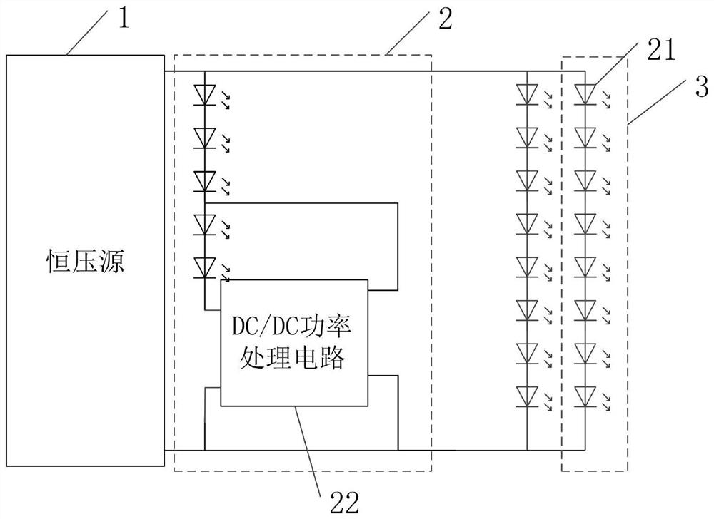
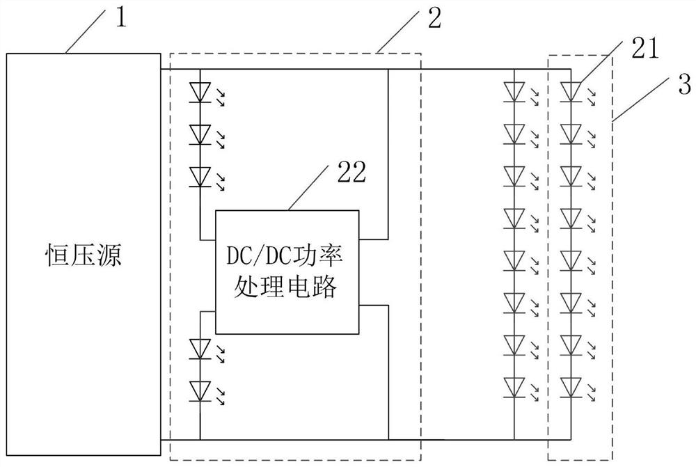
[0038] Such as Figure 1-8 As shown, the embodiment of this specification provides an LED drive system for plant lighting, including:

[0039] constant voltage source 1,

[0040] At least one first LED circuit 2, the first LED circuit 2 is electrically connected to both ends of the constant voltage source 1, the first LED circuit 2 includes a plurality of lamp bead units and a DC / DC power processing circuit 22, the DC / DC power processing circuit 22 through its positive input terminal, negative input terminal and multiple lamp bead units in series in sequence, the positive output terminal of the DC / DC power processing circuit 22 is electrically connected to the positive pole of one of the lamp bead units in the first LED circuit 2, and the DC / DC The negative output terminal of the power processing circuit 22 is electrically connected to the negative terminal of the constant voltage source 1, the lamp bead unit is composed of at least one LED lamp bead 21, and the DC / DC power p...

Embodiment approach

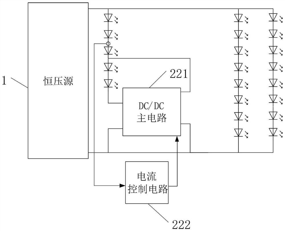
[0051] In one embodiment, as image 3 As shown, the DC / DC power processing circuit 22 includes a DC / DC main circuit 221 and a current control circuit 222, the current control circuit 222 includes a proportional integral circuit, and the current control circuit 222 is set to pass the detected current of the first LED circuit 2 The value is input into the proportional integral circuit so that the output voltage amplitude of the proportional integral circuit adjusts the input power of the DC / DC main circuit 221 to control the current value of the first LED circuit 2 to be equal to the current preset value, and the output voltage amplitude of the proportional integral circuit The value and the difference between the detected current value of the first LED circuit 2 and the current preset value are in a proportional-integral relationship.

[0052] Wherein, the current control circuit 222 is used to detect the current of the first LED circuit 2 connected to the input end of the DC / D...

Embodiment 2

[0070] The embodiment of this specification provides a plant lighting system, including multiple LED drive systems for plant lighting in Embodiment 1. A plant lighting system includes a plurality of LED driving systems in Embodiment 1, that is, includes a plurality of constant voltage sources 1, and each constant voltage source 1 is electrically connected to a plurality of first LED circuits equipped with a DC / DC power processing circuit 22 2. It is convenient to realize accurate control of LED driving systems corresponding to different plant lighting areas.


PUM


Abstract

The invention relates to an LED driving system for plant illumination and a plant illumination system.The LED driving system comprises a constant voltage source and at least one first LED circuit, the first LED circuit is electrically connected to the two ends of the constant voltage source, and the first LED circuit comprises a plurality of lamp bead units and a DC / DC power processing circuit; the DC / DC power processing circuit is sequentially connected with the plurality of lamp bead units in series through the positive input end and the negative input end of the DC / DC power processing circuit, the positive output end of the DC / DC power processing circuit is electrically connected to the positive electrode of one lamp bead unit in the first LED circuit, and the negative output end of the DC / DC power processing circuit is electrically connected to the negative end of the constant voltage source; the lamp bead unit is composed of at least one LED lamp bead, and the second LED circuit is electrically connected to the two ends of the constant voltage source. By arranging the DC / DC power processing circuit, the voltage of part of the lamp bead units can be converted into another DC voltage to be supplied to the first LED circuit again, so that the lighting efficiency of the lighting system is improved.

Description

technical field [0001] The invention relates to the technical field of plant lighting, in particular to an LED driving system and a plant lighting system for plant lighting. Background technique [0002] In the traditional multi-channel lighting system, a constant voltage source supplies power to multiple LED light sources. Therefore, it is necessary to select a constant voltage source with an output voltage higher than the voltage of the LED lamps of all branches to ensure that each LED lamp can emit light. Moreover, in order to make the light emitted by each LED lamp consistent, a current limiting module needs to be connected in series with each LED to limit the current of the branch to not exceed a preset value. [0003] However, in the indoor lighting system of the plant factory or the supplementary lighting system of the plant, each LED lamp forms an LED lamp, and the plant cultivation area is different, that is, the lighting area of ​​each corresponding LED lamp is dif...

Claims


Application Information

Patent Timeline
Patent Type & Authority Applications(China)
IPC IPC(8): H05B45/30H05B45/34
CPCH05B45/30H05B45/34
Inventor 华桂潮葛良安
Owner 4D BIOS INC
Why Eureka
Try Eureka