Insulation column cleaning system with liquid spraying mechanism
A cleaning system and insulating column technology, applied in vehicle cleaning, liquid cleaning methods, vehicle cleaning equipment, etc., can solve problems affecting the safety of railway transportation, cleaning dead ends, tripping of transmission lines, etc., to achieve cleaning automation, Solve the effect of cleaning dead corners and avoiding waste
- Summary
- Abstract
- Description
- Claims
- Application Information
AI Technical Summary
Problems solved by technology
Method used
Image
Examples
Embodiment 1
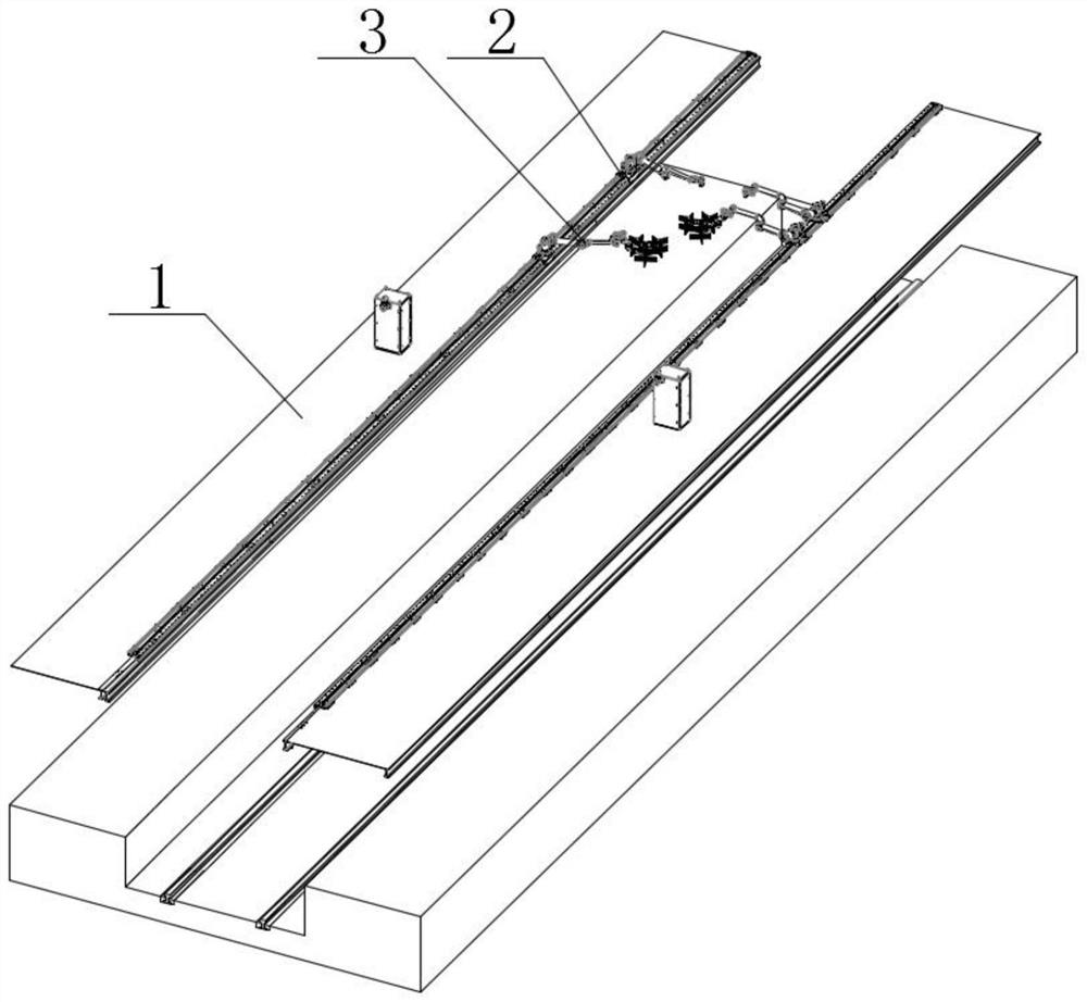
[0038] Such as figure 1 , figure 2 , image 3 As shown, the insulating column cleaning system with a liquid spray mechanism in this embodiment includes a substrate 1 and an insulating column 5 arranged above the train. The substrate 1 is arranged on both sides of the train track and is parallel to the train track. There is a walking unit 2 that moves along the direction of the train. The walking unit 2 is provided with a mechanical arm unit 3. The mechanical arm unit 3 is provided with a cleaning unit 4 for cleaning the insulating column 5. The mechanical arm unit 3 drives the cleaning unit 4 to move in any direction. ;
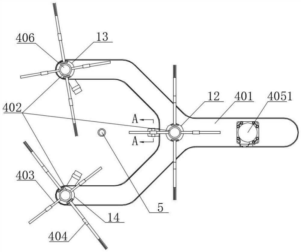
[0039] The cleaning unit 4 includes a Y-shaped support base 401, a rotating shaft 402 is arranged on the Y-shaped supporting base 401, a hair brush 404 for scrubbing the insulating column 5 is arranged on the rotating shaft 402, and a liquid spraying device for spraying the insulating column 5 mechanism.
[0040] In the insulating column cleaning system ...
Embodiment 2
[0043] Quoted from Example 1.
[0044] Such as image 3 As shown, the rotating shaft 402 is a cylinder with an open upper end and a hollow interior; the liquid spray mechanism includes a liquid spray tube 403 and an infusion tube 406, the liquid spray tube 403 is connected through the cylinder, and one end of the infusion tube 406 is movably inserted into the cylinder. The infusion tube 406 is fixedly arranged on the Y-shaped support base 401 and connected with the inner wall of the cylinder with a mechanical seal.
[0045] In the liquid spraying mechanism, the cleaning liquid is sprayed to the insulating column 5 by the liquid spraying pipe 403 through the infusion tube 406 and the rotating shaft 402 .
Embodiment 3
[0047] Extracted from Example 2.
[0048] Such as image 3 , Figure 4 As shown, the connection mode between the Y-shaped support base 401 and the rotating shaft 402 is a rotational connection, and the Y-shaped support base 401 is provided with a driving mechanism 405 that drives the rotating shaft 402 to rotate; the infusion tube 406 is connected with the inner wall of the cylinder with a mechanical seal to meet The position of the infusion tube 406 is fixed, the rotation of the rotating shaft 402 requires the seal between the infusion tube 406 and the rotating shaft 402;
[0049] Such as Figure 5 As shown, the driving mechanism 405 includes a motor 4051 arranged on the Y-shaped support base 401, the output end of the motor 4051 is connected with a transmission gear 4052; The moving gear 4053 is connected with the same transmission chain 4054; the Y-shaped support base 401 is provided with a limiting gear 4055 for limiting the transmission chain 4054.
[0050] The motor ...
PUM
 Abstract
Description
Claims
Application Information
 - R&D
- Intellectual Property
- Life Sciences
- Materials
- Tech Scout
- Unparalleled Data Quality
- Higher Quality Content
- 60% Fewer Hallucinations
Browse by: Latest US Patents, China's latest patents, Technical Efficacy Thesaurus, Application Domain, Technology Topic, Popular Technical Reports.
© 2025 PatSnap. All rights reserved.Legal|Privacy policy|Modern Slavery Act Transparency Statement|Sitemap|About US| Contact US: help@patsnap.com


