An underwater manipulator

An underwater manipulator and manipulator technology, applied in the field of manipulators, can solve the problems of limited working range, high manufacturing cost, manipulator function and complex structure, etc.

Active Publication Date: 2022-05-03
GUANGDONG OCEAN UNIVERSITY
View PDF9 Cites 0 Cited by
  • Summary
  • Abstract
  • Description
  • Claims
  • Application Information

AI Technical Summary

Problems solved by technology

[0003] A manipulator is an automatic operating device that can imitate certain movements of the human hand and arm to grab, carry objects or operate tools according to a fixed program. Distance operation, the movement of the manipulator is carried out by the movement of the underwater robot or the movement of the hull on the water. The manipulator cannot move for a long distance and its working range is limited
And the existing manipulator function and structure are all too complicated, and the manufacturing cost is too high

Method used


Image

  • An underwater manipulator
  • An underwater manipulator
  • An underwater manipulator

Examples


Embodiment 1

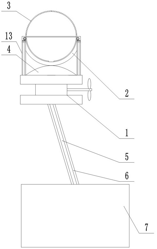
[0027] refer to Figure 1-3 , the present embodiment provides an underwater manipulator, including a mounting plate 1, the mounting plate 1 is connected with a lifting part for controlling the lifting of the mounting plate 1 and a driving part for controlling the horizontal movement of the mounting plate 1; one side of the mounting plate 1 A manipulator main body 2 is fixedly arranged, and a plurality of mechanical claws 3 are slidably connected inside the manipulator main body 2, and each mechanical claw 3 is controlled to rotate by a control unit. The present invention directly controls the lifting of the mounting plate 1 through the lifting part, and drives the mounting plate 1 to move in a certain plane in the water through the driving part, so that the manipulator can move freely within a specific range, so that it can move for a long distance and reduce the size of the water hull or The underwater robot 7 restricts it, and controls the mechanical claw 3 to slide inside t...

Embodiment 2

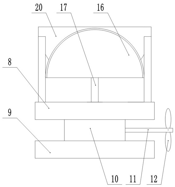
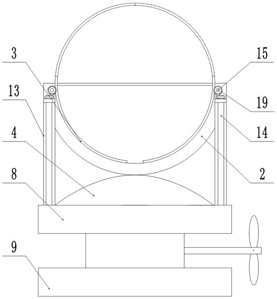
[0034] refer to Figure 4-5 , this embodiment provides an underwater manipulator. The difference between this embodiment and Embodiment 1 is that the main body of the manipulator 2 is a hollow hemispherical structure, and the mechanical claw 3 is a three-dimensional arc adapted to the hollow hemispherical structure of the manipulator main body 2. Shaped structure, present embodiment is suitable for grasping the article of approximation and spherical structure.

[0035] To further optimize the scheme, the three-dimensional arc of the mechanical claw 3 is a three-point structure, the first end point of the mechanical claw 3 is set at the uppermost part of the mechanical claw 3, and the second end point and the third end point of the mechanical claw 3 are both set at the bottom and at the bottom. The same horizontal line, which is similar to the pattern on the watermelon; the number of mechanical claws 3 is arranged in no less than three groups, and the distance between adjacent ...


PUM


Abstract

The invention discloses an underwater manipulator, which comprises a mounting plate connected with a lifting part for controlling the lifting of the mounting plate and a driving part for controlling the horizontal movement of the mounting plate; a manipulator main body is fixedly arranged on one side of the mounting plate. A plurality of mechanical claws are slidingly connected inside, and each mechanical claw is controlled to rotate by the control part. The invention directly controls the lifting of the mounting plate through the lifting part, and drives the mounting plate to move in a certain plane in the water through the driving part, so that the manipulator can move freely within a specific range, so that it can move for a long distance, and reduce the size of the hull on the water or water. Under the restriction of the robot, and through the control part to control the sliding of the mechanical claws inside the main body of the manipulator, multiple sets of mechanical claws can work synchronously to realize grabbing, dragging and other work, and can realize most of the underwater operations on the seabed.

Description

technical field [0001] The invention relates to the technical field of manipulators, in particular to an underwater manipulator. Background technique [0002] The ocean is rich in biological resources, mineral resources and a large amount of energy such as oil, coal and natural gas. Many countries have realized the importance of using and developing the ocean, and have invested a lot of money, manpower, and material resources in research work in this area. The status of marine resource development, marine environment and climate research, inland waterway transportation, and water resource utilization in the national economy determines the significance of developing underwater technology and underwater operating systems. Various underwater robots are unanimously recognized by marine scientists as the most important basic technology for developing marine resources. Underwater robots can be widely used in many aspects such as seabed mineral resource development, sea rescue an...

Claims


Application Information

Patent Timeline
Patent Type & Authority Patents(China)
IPC IPC(8): B25J11/00B63C11/52B63H5/07B25J18/00
CPCB63H5/07B25J11/00B63C11/52B25J18/00
Inventor 李依潼王骥
Owner GUANGDONG OCEAN UNIVERSITY
Why Eureka
Try Eureka