
High-temperature and high-pressure single-rod critical heat flux density visualization experiment device

A technology of critical heat flux, high temperature and high pressure, applied in the field of high temperature and high pressure single-rod critical heat flux visualization experimental device, can solve the problems of thermal expansion of heating rod, difficulty in realization, difficulty in insulation and sealing of heating rod, etc., to prevent bending or damage, and overcome heat flow The effect of high density, convenient shooting and light source arrangement

Pending Publication Date: 2022-03-25
XI AN JIAOTONG UNIV +1
View PDF0 Cites 1 Cited by
  • Summary
  • Abstract
  • Description
  • Claims
  • Application Information

AI Technical Summary

Problems solved by technology

However, it is very difficult to realize the above-mentioned experimental device, and the existing CHF experimental device and technology are no longer applicable
On the one hand, the visualization experiment technology is widely used under low temperature and low pressure conditions, but it is difficult to realize under high temperature and high pressure; on the other hand, the CHF experiment on the rod surface needs to use high-power direct electric heating rods, and the wall temperature is high when CHF occurs under high temperature and high pressure conditions. , the heating rod will undergo significant thermal expansion, which will bring great difficulties to the insulation and sealing of the heating rod

Method used


Image

  • High-temperature and high-pressure single-rod critical heat flux density visualization experiment device
  • High-temperature and high-pressure single-rod critical heat flux density visualization experiment device
  • High-temperature and high-pressure single-rod critical heat flux density visualization experiment device

Examples


Embodiment Construction

[0036] The technical solutions in the embodiments of the present invention will be clearly and completely described below in conjunction with the accompanying drawings in the embodiments of the present invention. Obviously, the described embodiments are only some of the embodiments of the present invention, not all of them. Based on the embodiments of the present invention, all other embodiments obtained by persons of ordinary skill in the art without making creative efforts belong to the protection scope of the present invention.

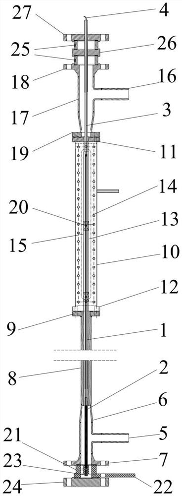
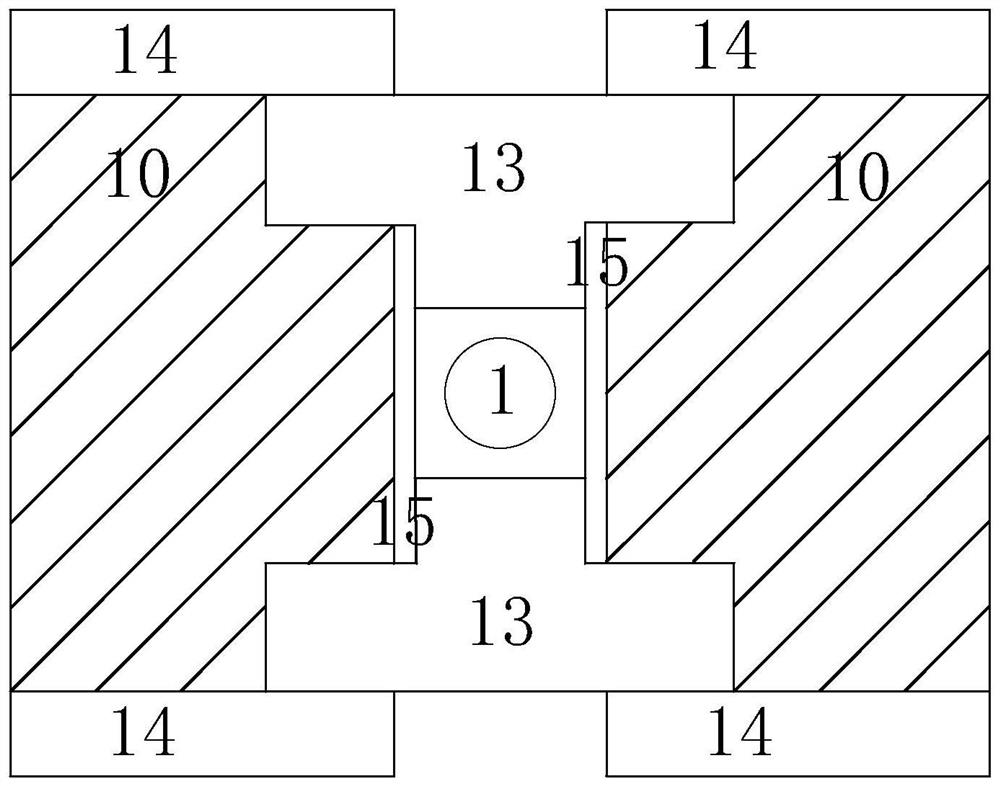
[0037] see Figure 1 to Figure 3 , the embodiment of the present invention provides a high-temperature and high-pressure single-rod critical heat flux visualization experimental device, which includes a central inner rod and an insulating support structure. segment, visible segment, outlet segment and inside the top seal structure.

[0038] The central inner rod includes a heating rod 1, a non-heating rod 2 at the bottom, a non-heating rod 3 at th...


PUM


Abstract

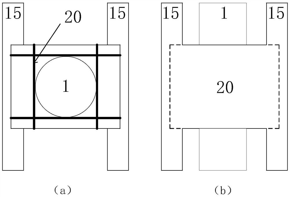
The invention discloses a high-temperature and high-pressure single-rod critical heat flux density visualization experiment device, which comprises a central inner rod and an insulating support structure, and is characterized in that the central inner rod is arranged in a bottom end sealing structure, an inlet section, a square cavity section, a visual section, an outlet section and a top end sealing structure which are sequentially connected from bottom to top; the central inner rod comprises a heating rod, a bottom end non-heating rod connected to the bottom end of the heating rod, a top end non-heating rod connected to the top end of the heating rod, and a sheathed thermocouple arranged in the heating rod; the top end non-heating rod and the sheathed thermocouple extend out of the top end sealing structure; the insulating supporting structure comprises supporting grillwork and insulating ceramics, the supporting grillwork is used for fixing and limiting the central inner rod, and a plurality of supporting grillwork are arranged in the axial direction of the central inner rod; the insulating ceramics are tightly arranged on the inner surface of the frame of the square cavity section and are used for fixing and limiting the supporting grillwork. According to the invention, the deficiency of a high-temperature and high-pressure experimental section in a reactor fuel rod surface critical heat flux density experiment is filled up.

Description

technical field [0001] The invention belongs to the technical field of nuclear reactor thermal-hydraulic experiments, and in particular relates to a high-temperature and high-pressure single-rod critical heat flux visualization experimental device. Background technique [0002] The critical heat flux (CHF) is an important thermal limit to characterize the safety and economics of a nuclear reactor under normal or accidental conditions. Experimental research on CHF in fuel bundle channels is of great significance, which is the prerequisite for obtaining effective data of CHF in bundles and establishing accurate prediction tools for CHF. In engineering, under the operating parameters of the actual reactor primary loop, large-scale direct electric heating rod bundle structures are often used for CHF experiments. The obtained rod bundle CHF data can be used for the development of CHF relational expressions and guide engineering design. However, the cost of CHF rod beam engineeri...

Claims


Application Information

Patent Timeline
Patent Type & Authority Applications(China)
IPC IPC(8): G01N25/20
CPCG01N25/20
Inventor 桂淼刘扬单建强郭俊良单嘉润
Owner XI AN JIAOTONG UNIV
Learn More