Skid-mounted hydrogen refueling station

A hydrogen refueling station, skid-mounted technology, applied in the field of hydrogen refueling equipment, can solve problems such as inconvenience, and achieve the effects of reducing costs, not easy to fall off naturally, and stable connection

Active Publication Date: 2022-03-25
BEIJING SANKI GASOLINEEUM TECH
View PDF10 Cites 0 Cited by
  • Summary
  • Abstract
  • Description
  • Claims
  • Application Information

AI Technical Summary

Problems solved by technology

The skid-mounted hydrogen refueling station has the advantages of compact equipment, small footprint, and short on-site construction period. However, due to the large mass of the skid-mounted hydrogen refueling station, it is inconvenient to use a crane to assist when loading

Method used


Image

  • Skid-mounted hydrogen refueling station
  • Skid-mounted hydrogen refueling station
  • Skid-mounted hydrogen refueling station

Examples


Embodiment 1

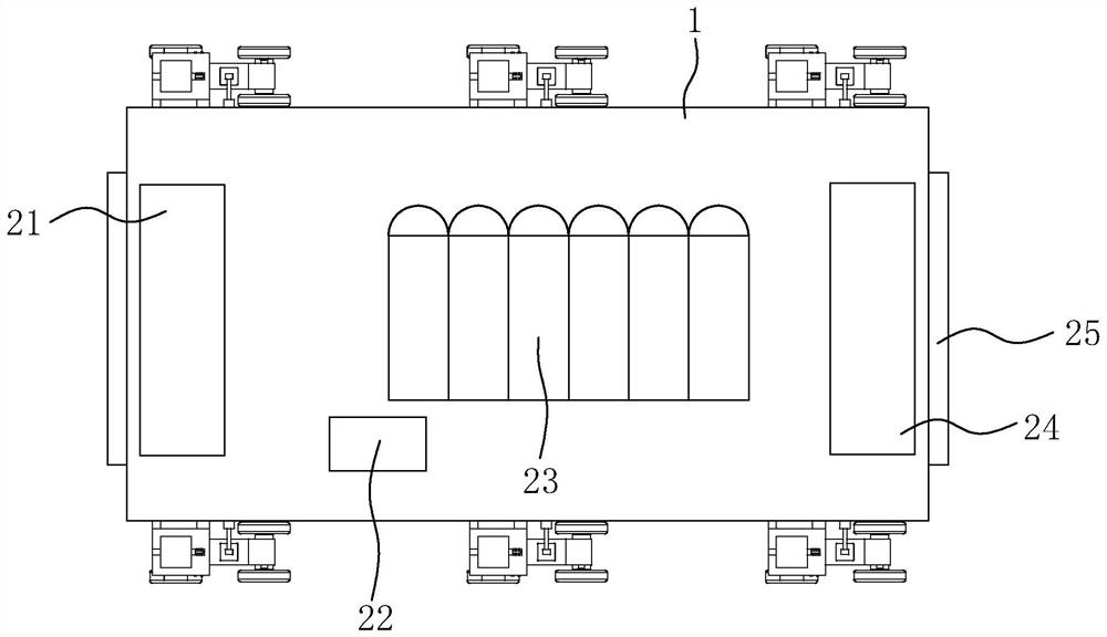
[0048] refer to figure 1, the skid-mounted hydrogen refueling station includes a chassis 1, an unloading column 21, a compressor 22, a hydrogen storage tank 23, and a filling machine 24. Both ends of the chassis 1 are equipped with electric rolling doors 25, an unloading column 21, and a compressor 22. , the hydrogen storage tank 23 and the filling machine 24 are all arranged in the cabinet 1, and the unloading column 21 and the filling machine 24 are respectively located at both ends of the cabinet 1, the unloading column 21, the compressor 22, the hydrogen storage tank 23 and the filling Machines 24 are connected in turn by pipelines.

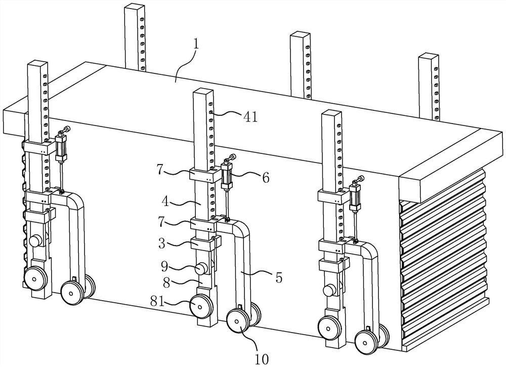
[0049] refer to figure 2 The skid-mounted hydrogen refueling station also includes at least three lifting systems installed outside the chassis 1. In this embodiment, there are six lifting systems, and the six lifting systems are evenly distributed on both sides of the chassis 1.

[0050] refer to figure 2 , the lifting system includes a...

Embodiment 2

[0066] The difference between this embodiment and Embodiment 1 is: refer to Figure 10 The limit pin 73 includes a pin rod 731, a button 732 fixedly connected to one end of the pin rod 731, a locking bar 733 arranged at the other end of the pin rod 731, and a second spring 734 sleeved on the pin rod 731. The pin rod 731 One end away from the button 732 is provided with a mounting groove, the locking bar 733 is arranged in the mounting groove and the middle part of the locking bar 733 is rotationally connected with the pin rod 731; the locking bar 733 can be accommodated in the mounting groove by rotation, or both ends Protrude out of the mounting slot.

[0067] The implementation principle of the second embodiment is: when it is necessary to install the limit pin 73 on the connecting seat 71, first rotate the locking bar 733, and store the locking bar 733 in the installation groove; then pass the pin bar 731 through the first The latch hole 75 or the second latch hole 76, and...


PUM


Abstract

The invention relates to hydrogenation equipment, in particular to a skid-mounted hydrogen refueling station, which comprises a case as well as a gas discharging column, a compressor, a hydrogen storage tank and a filling machine which are mounted in the case, and is characterized in that the skid-mounted hydrogen refueling station further comprises at least three lifting systems mounted outside the case; the lifting system comprises a stand column vertically connected to the machine box in a sliding mode, a connecting piece connected to the stand column, a hydraulic cylinder hinged between the connecting piece and the machine box and a supporting leg connected to the lower end of the stand column, and the supporting leg is hinged to the stand column and can slide in the length direction of the stand column. Locking assemblies used for locking the supporting legs are installed at the joints of the stand columns and the supporting legs. Supporting wheels are arranged on the connecting pieces, are vertically connected to the connecting pieces in a sliding mode and are always lower than the hinged positions of the stand columns and the supporting legs; the connecting piece is further provided with an inductor used for detecting displacement of the supporting wheel, and the inductor is electrically connected with the locking assembly. The skid-mounted hydrogen refueling station has the advantages that a crane does not need to be matched with a convenient loading vehicle, and transportation of the skid-mounted hydrogen refueling station is more convenient.

Description

technical field [0001] The present application relates to the field of hydrogen refueling equipment, in particular to a skid-mounted hydrogen refueling station. Background technique [0002] Hydrogen refueling stations are mainly divided into skid-mounted hydrogen refueling stations and fixed open hydrogen refueling stations. The skid-mounted hydrogen refueling station integrates all or part of the hydrogen booster equipment, hydrogen refueling machine, pipeline system, electrical system, instrument control system and safety accessories into a skid-mounted box. The skid-mounted hydrogen refueling station has the advantages of compact equipment, small footprint, and short on-site construction period. However, due to the large mass of the skid-mounted hydrogen refueling station, it is inconvenient to use a crane to assist when loading. [0003] The Chinese patent with the publication number CN207716085U discloses a gas-driven pump skid-mounted hydrogenation equipment, which i...

Claims


Application Information

Patent Timeline
Patent Type & Authority Applications(China)
IPC IPC(8): F17C1/00F17C7/00F17C13/08F17C5/06
CPCF17C1/00F17C7/00F17C13/08F17C5/06F17C2205/0161F17C2205/013Y02E60/32
Inventor 顾建辉卢永安吴立军崔保庄李刚钟伟明
Owner BEIJING SANKI GASOLINEEUM TECH
Why Eureka
Try Eureka