Rotary spinning head for electrostatic spinning device
An electrospinning and spinning head technology, which is applied to the field of rotary spinning heads for electrospinning machines, can solve problems such as affecting the diversity of spinning shapes and the spinning head cannot rotate, and achieves the effect of improving the driving force
- Summary
- Abstract
- Description
- Claims
- Application Information
AI Technical Summary
Problems solved by technology
Method used
Image

Examples
Embodiment 1
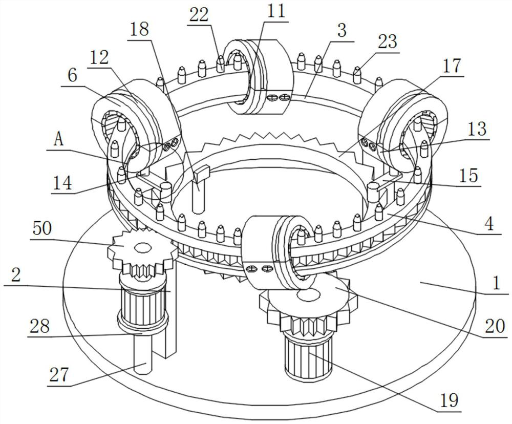
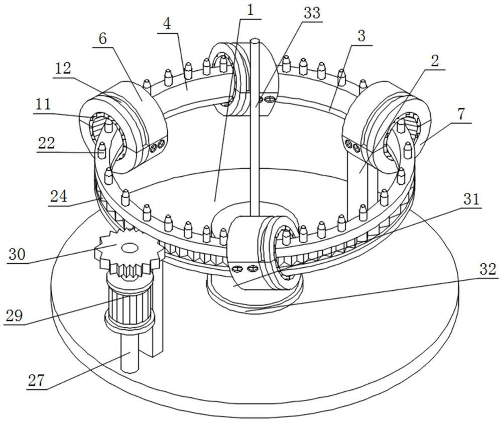
[0041] Such as figure 1 and image 3 As shown, a rotary spinning head for an electrospinner includes a circular bottom plate 1, a support plate 2, a circular plate 3 and a guide rail 4. Two sets of support plates 2 arranged front and back are installed on the top of the circular bottom plate 1, and two sets of A circular plate 3 is installed on the top of the support plate 2;
[0042] A guide rail 4 is installed on the top of the circular plate 3;
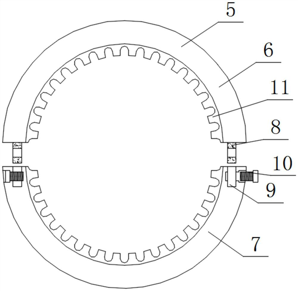
[0043] The outer surface of the guide rail 4 is connected in series with multiple sets of evenly arranged spinning head bodies 5. The spinning head body 5 consists of an upper combined ring 6, a lower combined ring 7, a fixed block 8, a groove 9, a locking nail 10 and a semi-circular Composed of helical gears 11, the bottom of the upper combined ring 6 is equipped with a lower combined ring 7, grooves 9 are arranged on both sides of the top of the lower combined ring 7, and fixed blocks 8 are installed on both sides of the bottom...
Embodiment 2
[0046] Such as figure 1 , Figure 4 and Figure 5 As shown, the outer surfaces of the upper combined ring 6 and the lower combined ring 7 are provided with annular grooves 12, wherein the inner walls of a group of annular grooves 12 are equipped with arc-shaped fitting plates 13, and the bottoms of the arc-shaped fitting plates 13 are equipped with connecting columns 14 , An engaging plate 15 is installed on the bottom of the connecting column 14, a fixing column 16 is installed on one end of the connecting plate 15, and a ring gear 17 is installed on the bottom of the fixing column 16.
[0047] Two groups of support members 18 arranged side by side are installed on the top of the round bottom plate 1, U-shaped plates are installed on the tops of the two groups of support members 18, and the top of the U-shaped plate fits with the bottom of the ring gear 17, and the top of the round bottom plate 1 A servomotor 19 is installed, and the output end of the servomotor 19 is equip...
Embodiment 3
[0050] Such as figure 1 and Figure 6 As shown, the top of the guide rail 4 is equipped with multiple groups of threaded rods 21 evenly arranged in a ring, the outer surfaces of the multiple groups of threaded rods 21 are equipped with connecting collars 22, and the tops of the connecting collars 22 are equipped with tapered push rods 23, And the top of the tapered push rod 23 is attached to the inner wall of the half-ring helical gear 11 .
[0051] Specifically, the inner thread of the connecting collar 22 and the thread provided on the outer surface of the threaded rod 21 can be matched with each other, thereby facilitating detachable assembly between the two. When the top of the tapered push rod 23 is seriously worn, the connecting Collar 22 exerts the rotational force of setting anticlockwise direction, in order to be out of contact between it and threaded rod 21, then facilitates the replacement of another group of new tapered push rods 23, in order to improve oneself to...
PUM
 Abstract
Description
Claims
Application Information
 - R&D
- Intellectual Property
- Life Sciences
- Materials
- Tech Scout
- Unparalleled Data Quality
- Higher Quality Content
- 60% Fewer Hallucinations
Browse by: Latest US Patents, China's latest patents, Technical Efficacy Thesaurus, Application Domain, Technology Topic, Popular Technical Reports.
© 2025 PatSnap. All rights reserved.Legal|Privacy policy|Modern Slavery Act Transparency Statement|Sitemap|About US| Contact US: help@patsnap.com