
Structure and method for preventing gas blow-by during pouring of multi-component casting mold for sand-lined iron mold casting

A technology of iron mold sand-covered casting and mold pouring, which is applied in the direction of casting molding equipment, molds, mold components, etc., can solve the problems of unsafe production, air hole defects, gas explosion and blasting, etc., achieve good results and simplify production Operation process, the effect of improving production efficiency

Pending Publication Date: 2022-03-22
浙江省机电设计研究院有限公司
View PDF7 Cites 0 Cited by
  • Summary
  • Abstract
  • Description
  • Claims
  • Application Information

AI Technical Summary

Problems solved by technology

During the pouring process, a large amount of gas generated in the casting cavity of the casting that is poured first often enters the cavity of the casting that is poured later, causing the cavity of the casting that is poured later to explode when the molten iron is poured, resulting in unsafe factors in production. , and the intruded gas enters the molten iron that is poured later, so that the casting that is poured into the mold will eventually cause porosity defects and be scrapped

Method used


Image

  • Structure and method for preventing gas blow-by during pouring of multi-component casting mold for sand-lined iron mold casting
  • Structure and method for preventing gas blow-by during pouring of multi-component casting mold for sand-lined iron mold casting
  • Structure and method for preventing gas blow-by during pouring of multi-component casting mold for sand-lined iron mold casting

Examples


Embodiment Construction

[0024] The present invention will be further described in detail below in conjunction with the accompanying drawings and examples. The following examples are explanations of the present invention and the present invention is not limited to the following examples.

[0025] Example.

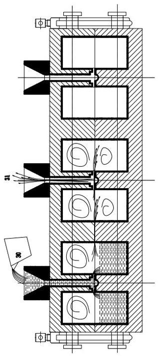
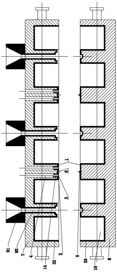
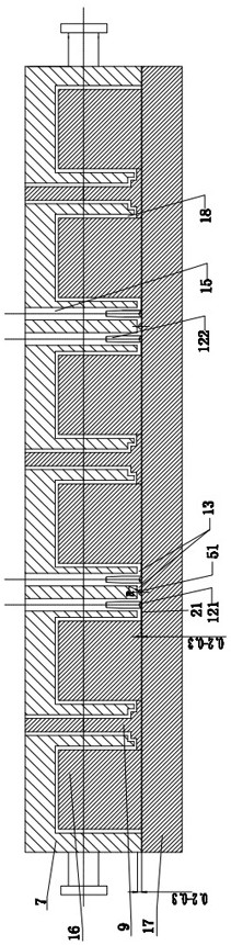
[0026] see Figure 1 to Figure 7 In this embodiment, the anti-channeling gas structure of the iron mold sand-coated casting multi-component casting mold includes an upper iron mold 7, a lower iron mold 8, an anti-channeling gas sand layer 1, two independent exhaust systems and a gas Partition system, one layer of anti-channeling gas-coated sand layer 1 is set on the parting plane of upper iron type 7 and lower iron type 8 respectively, and two independent exhaust systems and one gas partition system are arranged on the anti-channeling gas-coated layer 1 , the exhaust system includes an exhaust gap 2, an exhaust groove 3, and a plurality of exhaust holes 4 on the exhaust groove 3; the gas partition...


PUM


Abstract

The invention relates to a structure and a method for preventing gas blow-by during sand-lined iron mold casting pouring, and belongs to the field of machinery. The device comprises an upper iron mold, a lower iron mold, anti-gas-channeling sand-coated layers, two independent exhaust systems and a gas partition system, the parting planes of the upper iron mold and the lower iron mold are each provided with one anti-gas-channeling sand-coated layer, and the two independent exhaust systems and the gas partition system are arranged on the anti-gas-channeling sand-coated layers. The exhaust system comprises an exhaust gap, an exhaust groove and a plurality of exhaust holes in the exhaust groove; the gas blocking system comprises a gas blocking and isolating convex strip and a gas blocking and isolating groove which are matched with each other, the gas blocking and isolating convex strip is arranged between the two exhaust systems of the two adjacent components of the lower iron mold, and the gas blocking and isolating groove is arranged between the two exhaust systems of the two adjacent components of the upper iron mold. The mold is simple and reasonable in structural design, safe and reliable, the production efficiency of the iron mold is improved, the production operation procedure is simplified, the cost is low, and the use requirement is met.

Description

technical field [0001] The present invention relates to a structure and method for preventing blow-by gas during pouring of iron mold sand-covered casting multi-component casting molds, in particular to a tooling mold used in the production of iron mold sand-covered casting, especially in a pair of iron molds The mold structure of molten iron that needs to be poured multiple times in the sand-covered iron mold belongs to the field of machinery. Background technique [0002] Iron mold sand-coated casting belongs to special casting, and its mold is formed by covering a thin layer of coated sand on the inner cavity of the metal mold. Iron mold sand-covered casting has the characteristics of energy saving, material saving, high efficiency, high quality, green production, etc., and has been widely used. [0003] In the production of iron mold sand-covered castings, in order to improve production efficiency and meet the technological requirements of iron mold sand-covered casting...

Claims


Application Information

Patent Timeline
Patent Type & Authority Applications(China)
IPC IPC(8): B22C9/06B22C9/20
CPCB22C9/068B22C9/067B22C9/20
Inventor 潘东杰朱丹夏小江高强应浩朱国汤瑶胡鸿斌
Owner 浙江省机电设计研究院有限公司
Learn More