On-site reinforcing steel bar bending adjusting system for construction machinery

A mechanical and on-site technology, applied in the field of on-site steel bar bending system, can solve problems such as the inability to accurately grasp the angle of steel bar bending, the difference in the angle of steel bars, and the laborious use, so as to achieve safe and convenient use, good effect, and scientific and reasonable structure. Effect

Active Publication Date: 2022-03-18
JINLING INST OF TECH
View PDF22 Cites 1 Cited by
  • Summary
  • Abstract
  • Description
  • Claims
  • Application Information

AI Technical Summary

Problems solved by technology

[0004] The present invention provides an on-site steel bar bending system for construction machinery, which can effectively solve the problem of the current on-site steel bar bending system for construction machinery proposed in the background technology. The angle cannot be accurately grasped, resulting in a certain angle difference in the bent steel bar, which is more laborious in subsequent use

Method used


Image

  • On-site reinforcing steel bar bending adjusting system for construction machinery
  • On-site reinforcing steel bar bending adjusting system for construction machinery
  • On-site reinforcing steel bar bending adjusting system for construction machinery

Examples


Embodiment Construction

[0043] The preferred embodiments of the present invention will be described below in conjunction with the accompanying drawings. It should be understood that the preferred embodiments described here are only used to illustrate and explain the present invention, and are not intended to limit the present invention.

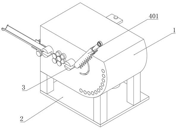
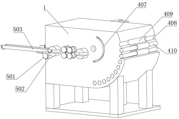
[0044] Example: such as Figure 1-4 As shown, the present invention provides a technical solution, an on-site steel bar bending system for construction machinery, including a bending seat 1, a base 2 is installed on the bottom of the bending seat 1, and a front end of the bending seat 1 is installed There is a steel bar block 3, and the front end of the bending seat 1 is equipped with a bending assembly 4;

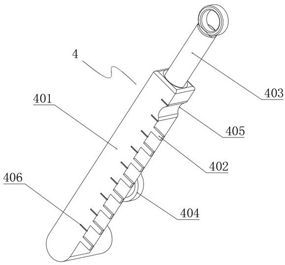
[0045] The bending assembly 4 includes a pressing rod 401, a stopper 402, a handle bar 403, a fixed block 404, a snap-in arc groove 405, a scale line 406, a rotating groove 407, a sliding hole 408, a limiting groove 409, a position limiting rod 410 and Limit cy...


PUM


Abstract

The invention discloses an on-site reinforcing steel bar bending adjusting system for construction machinery, which comprises a bending seat, the bottom of the bending seat is provided with a base, the front end face of the bending seat is provided with a reinforcing steel bar clamping block, and the front end of the bending seat is provided with a bending assembly.According to the on-site reinforcing steel bar bending adjusting system, a pressing rod is rotated to a horizontal state, and a reinforcing steel bar is pulled to a proper position according to scale marks; the position limiting rod at the corresponding position is pushed out of the sliding hole, the handheld rod is held to press the reinforcing steel bar downwards until the clamping arc groove in one end of the pressing rod is clamped with the pushed-out position limiting rod, after bending is completed, the position limiting rod is pushed into the sliding hole, then the pressing rod is rotated upwards, and finally the reinforcing steel bar is pulled out and taken away. By pushing the position limiting rods at different positions, different bending angles can be adjusted, the steel bars can be bent conveniently, the bending angles of the steel bars are adjustable, the multiple steel bars can be bent by the same angle through limiting of the position limiting rods, and the steel bar bending effect is better.

Description

technical field [0001] The invention relates to the technical field of steel bar bending, in particular to an on-site steel bar bending system for construction machinery. Background technique [0002] Reinforcement refers to steel for reinforced concrete and prestressed reinforced concrete, which is circular in cross-section and sometimes square with rounded corners. Including smooth round steel bars, ribbed steel bars, and twisted steel bars. The steel bars are usually straight. During construction, the steel bars will be bent according to the needs, so that the steel bars can reach the desired curvature, which is convenient for construction and use; [0003] However, the current on-site steel bar bending system of construction machinery is not only laborious when bending steel bars, but also the bending angle of steel bars cannot be accurately grasped, resulting in a certain angle difference between bent steel bars, which is more laborious in subsequent use. . Contents ...

Claims


Application Information

Patent Timeline
Patent Type & Authority Applications(China)
IPC IPC(8): B21F1/00B21C51/00
CPCB21F1/00B21C51/00
Inventor 王书明张盖陈砚秋
Owner JINLING INST OF TECH
Why Eureka
Try Eureka