
Anti-blinking head limiting device for ophthalmologic medical operation

A limit device and head technology, applied in ophthalmology treatment, surgery, operating table, etc., can solve the problems of patient discomfort, reduce the comfort of the device, increase the pain of the patient, etc., so as to improve the convenience of use and ensure the stability , the effect of improving comfort

Inactive Publication Date: 2022-03-15
方月云
View PDF2 Cites 2 Cited by
  • Summary
  • Abstract
  • Description
  • Claims
  • Application Information

AI Technical Summary

Problems solved by technology

[0005] The object of the present invention is to provide a kind of anti-blink head restraint device that is used for ophthalmic medical operation, to solve the existing head restraint device on the market that the above-mentioned background technology proposes can't handle patient's eyelid, during operation During the process, the patient is prone to blinking, and additional tools are required to manually limit the patient's eyelids. The tools are easy to touch the patient's eyeballs and cause discomfort to the patient. At the same time, the operation risk is increased. The follow-up operation is inconvenient. Some methods of clamping and pulling the eyelids will cause Increases the patient's pain and reduces the comfort of the device

Method used


Image

  • Anti-blinking head limiting device for ophthalmologic medical operation
  • Anti-blinking head limiting device for ophthalmologic medical operation
  • Anti-blinking head limiting device for ophthalmologic medical operation

Examples


Embodiment Construction

[0042] The following will clearly and completely describe the technical solutions in the embodiments of the present invention with reference to the accompanying drawings in the embodiments of the present invention. Obviously, the described embodiments are only some, not all, embodiments of the present invention. Based on the embodiments of the present invention, all other embodiments obtained by persons of ordinary skill in the art without making creative efforts belong to the protection scope of the present invention.

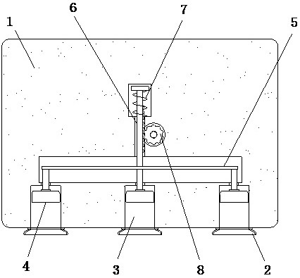
[0043] see Figure 1-8 , the present invention provides a technical solution: an anti-blink head stop device for ophthalmic medical surgery, including a support base 1 and a clamp block 10, the support base 1 is placed on the bed body to support the patient's head, and the clamp block The block 10 is set on the inner side of the support seat 1 to clamp and limit the two sides of the head. The outside of the clamp block 10 is connected with the support seat 1 thr...


PUM


Abstract

The invention discloses an anti-blink head limiting device for ophthalmology medical surgery, which comprises a supporting seat and clamping blocks, the supporting seat is placed on a bed body to support the head of a patient, the clamping blocks are arranged on the inner side of the supporting seat to clamp and limit the two sides of the head, and the outer sides of the clamping blocks are connected with the supporting seat through second springs. And clamping thrust is provided for the clamping block through the second spring, a guide block is fixed to the rear side of the clamping block, the clamping block and the supporting base form a left-right sliding structure through the guide block, and a first limiting block is arranged in the guide block. The anti-blink head limiting device for the ophthalmologic medical operation is provided with an eyelid control block and a flexible connector, the flexible connector is matched with a hollow suction cup to adsorb eyelids, the position of the eyelids can be controlled by matching with movement of the eyelid control block, the eyelids cannot make contact with eyeballs, operation is safer, and the device is more convenient to use. And the eyelids of the patient are not greatly painful, so that the subsequent use comfort is improved.

Description

technical field [0001] The invention relates to the technical field of ophthalmic medical surgery, in particular to an anti-blink head stopper for ophthalmic medical surgery. Background technique [0002] In the process of ophthalmology treatment, eye problems such as retinal diseases and myopia can be treated through eye surgery. During the operation, since the operation needs to be performed directly on the eyeball, it is necessary to ensure the stability of the patient's eye , the patient's head can be limited by the head restraint device before the operation, so that it remains stable during the operation, but the existing head restraint device still has some shortcomings when used: [0003] For example, the head fixing device disclosed by the publication number CN206372241U is used in ophthalmic surgery. In actual use, the head is supported by the moving plate, and the limit on both sides of the bottom of the head is completed by the lateral limit column. The limit ban...

Claims


Application Information

Patent Timeline
IPC IPC(8): A61G13/12A61G13/10A61B90/14A61B90/17A61F9/00A61B17/02
CPCA61G13/121A61G13/101A61B90/14A61B90/17A61F9/00A61B17/0231
Inventor 方月云
Owner 方月云
Learn More