
Feeding system hoisting mechanism

A technology of feeding system and feeding device, which is applied in cranes, hoisting devices, transportation and packaging, etc., can solve the problems of difficult work, easy dripping, excessive energy consumption, etc., and achieves easy operation and maintenance, good Cooperate and facilitate the effect of feeding system

Pending Publication Date: 2022-03-04
ZHENJIANG LANBO ENG TECH
View PDF0 Cites 0 Cited by
  • Summary
  • Abstract
  • Description
  • Claims
  • Application Information

AI Technical Summary

Problems solved by technology

[0002] In the automatic painting operation in the factory building of large bridges, the use of crane-type painting robots has achieved good results in site construction and practical application, but because the horizontal and vertical dimensions of the painting factory building are generally more than 50m×30m , the headroom height is above 9m. When the lifting stroke of the crane painting robot meets the requirements of site space utilization, the pipeline of the feeding system will be too long, usually exceeding the normal feeding length of more than 50m, resulting in insufficient atomization of the spray gun and scattered The reduction will affect the efficiency, increase the energy consumption, and waste the power of the air compressor. If the feeding system is fixed on the body of the crane-type painting robot, although the pipeline of the feeding system can be greatly shortened, before the painting operation, It is difficult to carry paint, paint mixing and mixing work at high altitudes in time, and the work is difficult; after the painting operation is completed, cleaning and maintenance of the feeding system at high altitudes will also become difficult and pose a safety hazard, and at the same time, it is easy to drip thinner Or paint onto the finished work surface, increasing the workload of manual repair

Method used

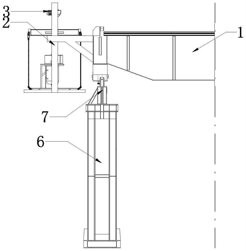
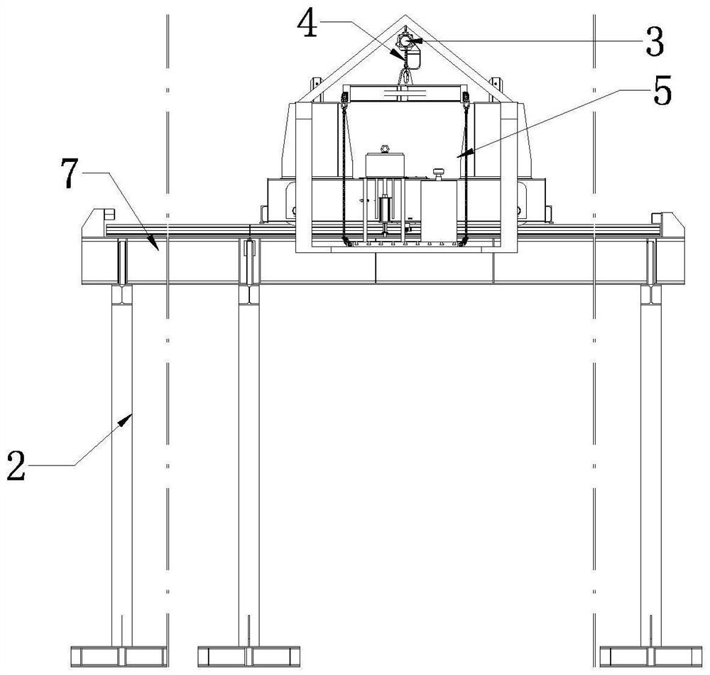
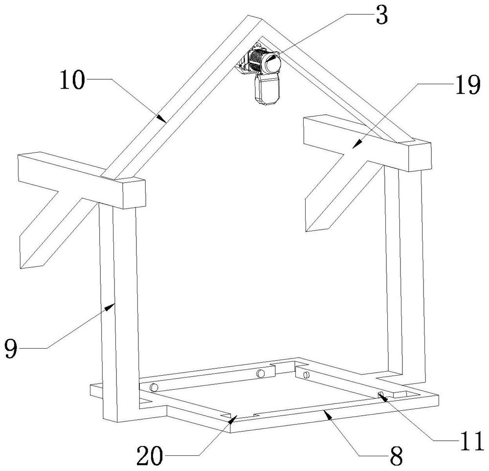

Image

  • Feeding system hoisting mechanism
  • Feeding system hoisting mechanism
  • Feeding system hoisting mechanism

Examples


Embodiment Construction

[0020] The hoisting mechanism of the feeding system of the present invention will be further described in detail below in conjunction with the accompanying drawings and specific embodiments.

[0021] For the automatic painting operation in the factory building of large bridges, as mentioned in the background technology, it is usually necessary to install the painting robot on the crane so that the painting robot can move back and forth in the factory building to achieve painting. The feeding system of the present invention is hoisted The mechanism is a new solution to the defect that the existing feeding system is fixed on the main body of the crane-type painting robot. As shown in the figure, it includes a hoisting bracket fixedly installed on the left end of the upper beam 1 of the crane 2 and the remote control electric hoist 3 fixedly installed on the top of the hoisting bracket 2, and the upper beam 1 is equipped with a figure 1 The left-right direction of the directions ...


PUM


Abstract

The invention discloses a hoisting mechanism of a feeding system. The hoisting support is fixedly installed on an upper cross beam of a crown block and can longitudinally reciprocate along with the upper cross beam, and the remote control electric hoist is fixedly installed at the top in the hoisting support and connected with a hoisting platform capable of being driven by the remote control electric hoist to ascend and descend through a sling. A feeding device used for feeding materials to the paint spraying equipment is fixedly installed on the hoisting platform, the paint spraying equipment can transversely move on the upper cross beam in a reciprocating mode relative to the hoisting support to conduct paint spraying operation, and the hoisting platform can ascend to the inner side of the hoisting support through driving of the remote control electric hoist to feed the materials to the paint spraying equipment. The feeding system has the advantages that the pipeline of the feeding system is shortened, the convenience of actual operation is increased, the feeding system and crown block type robot equipment are well matched, the combination of the large-range stroke of a crown block type paint spraying robot in a bridge painting room and the high utilization rate of a site is considered, and the feeding system is conveniently and practically operated and maintained.

Description

technical field [0001] The invention relates to equipment for bridge painting, in particular to a feeding system hoisting mechanism used on a painting crane robot. Background technique [0002] In the automatic painting operation in the factory building of large bridges, the use of crane-type painting robots has achieved good results in site construction and practical application, but because the horizontal and vertical dimensions of the painting factory building are generally more than 50m×30m , the headroom height is above 9m. When the lifting stroke of the crane painting robot meets the requirements of site space utilization, the pipeline of the feeding system will be too long, usually exceeding the normal feeding length of more than 50m, resulting in insufficient atomization of the spray gun and scattered The reduction will affect the efficiency, increase the energy consumption, and waste the power of the air compressor. If the feeding system is fixed on the body of the ...

Claims


Application Information

Patent Timeline
Patent Type & Authority Applications(China)
IPC IPC(8): B66C17/06B66C5/02B66C13/40B66C1/16
CPCB66C17/06B66C5/02B66C13/40B66C1/16
Inventor 胡颖健李鸿伟殷蕾厉志成
Owner ZHENJIANG LANBO ENG TECH
Learn More