High-low voltage distribution switch control cabinet for transformer substation

A technology for power distribution switches and control cabinets, which is applied in the details of substation/switch layout, cooling/ventilation of substation/switchgear, electrical components, etc. Inconvenience and other problems, to achieve the effect of improving convenience, improving service life, and improving flexibility

Pending Publication Date: 2022-03-01
徐州华创电子有限公司
View PDF0 Cites 2 Cited by
  • Summary
  • Abstract
  • Description
  • Claims
  • Application Information

AI Technical Summary

Problems solved by technology

[0003] 1. At present, in the traditional distribution cabinets for substations, the installation of electrical equipment is mostly fixed and installed inside the distribution cabinets by bolts. At the same time, according to the actual situation of the transmission circuit of the substation, the distribution cabinets needed The specifications of the power distribution cabinet are also very different. The specifications of the power distribution cabinet are: the size of the electrical equipment installed inside is different, which makes the installation of electrical equipment more inconvenient, and it is inconvenient to install electrical equipment of different heights;
[0004] 2. When the temperature of the electrical equipment in the power distribution cabinet is too high, it will affect the operating efficiency of the electrical equipment and affect the service life of the electrical equipment. Therefore, we propose a high and low voltage power distribution switch control cabinet for substations. solve the above problems

Method used


Image

  • High-low voltage distribution switch control cabinet for transformer substation
  • High-low voltage distribution switch control cabinet for transformer substation
  • High-low voltage distribution switch control cabinet for transformer substation

Examples


Embodiment

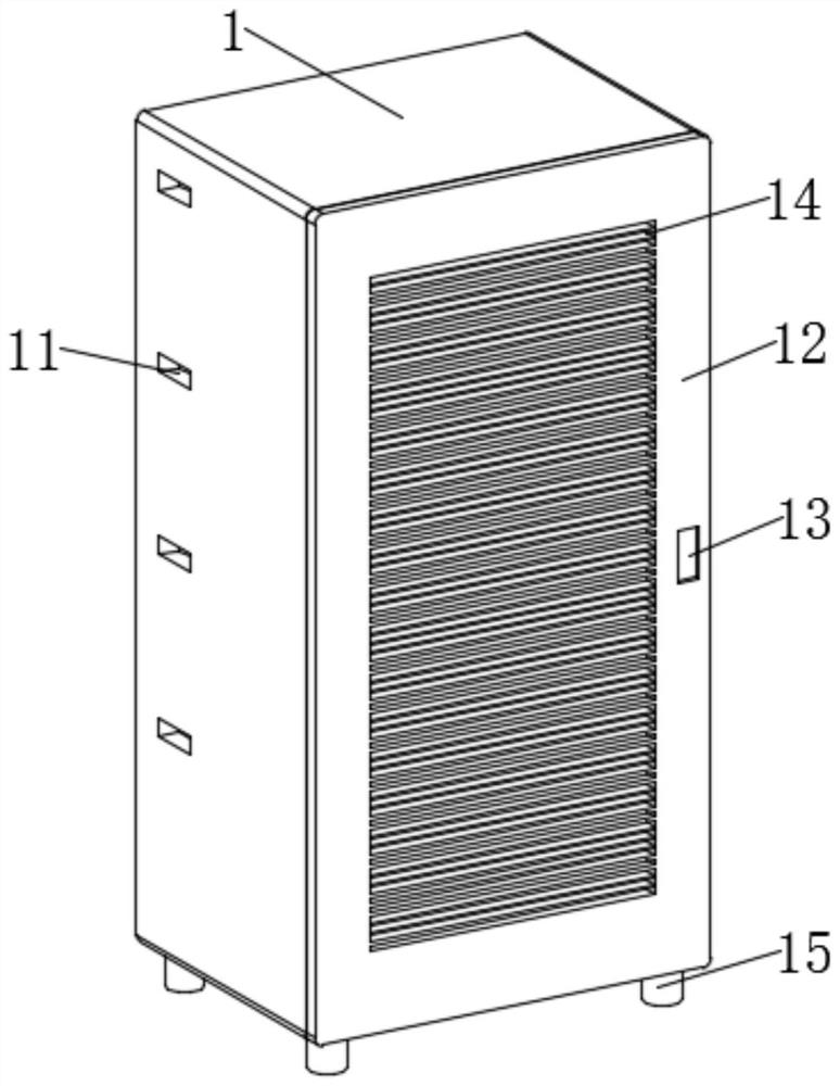
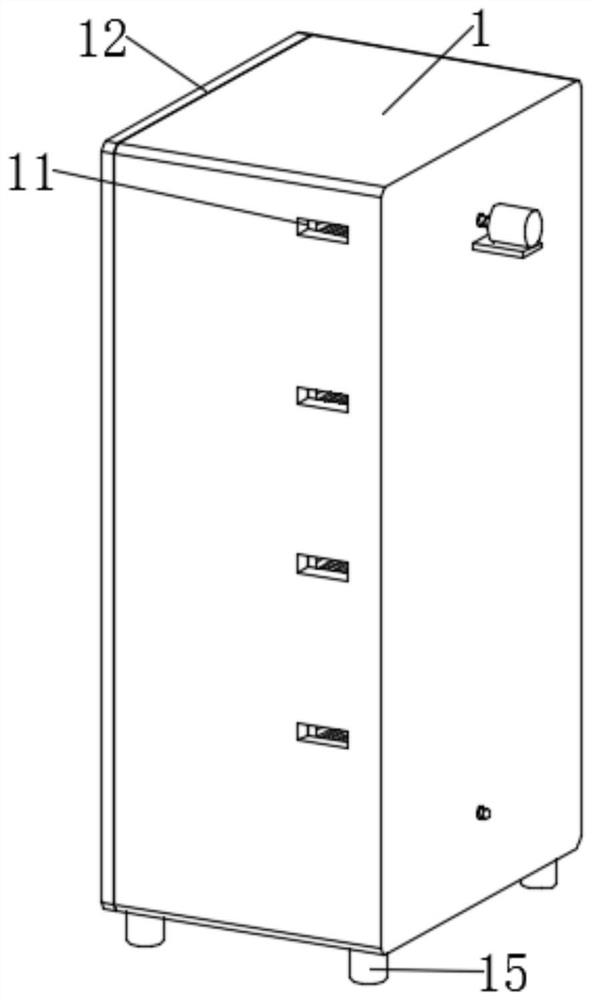
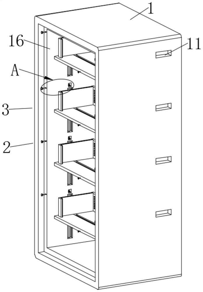
[0033] Example: such as Figure 1-11 As shown, the present invention provides a high and low voltage power distribution switch control cabinet for a substation, including a control cabinet body 1, one side of the control cabinet body 1 is rotatably connected with a door panel 12, and the surface of the door panel 12 is evenly distributed with the first A radiating groove 14, by opening the first radiating groove 14, the hot air flow in the control cabinet body 1 can be facilitated to flow to the outside of the control cabinet body 1, the inner wall of the control cabinet body 1 is fixedly installed with an inner frame 16, and the inner frame The inner walls on both sides of 16 are evenly distributed with first notches 161, and the height adjustment mechanism 2 is evenly distributed inside the inner frame 16. The height adjustment mechanism 2 can facilitate the installation of different electrical equipment, and the surface of the height adjustment mechanism 2 is provided with ...


PUM


Abstract

The invention discloses a high-low voltage power distribution switch control cabinet for a transformer substation, and particularly relates to the field of power distribution cabinets, the high-low voltage power distribution switch control cabinet comprises a control cabinet body, one side of the control cabinet body is rotatably connected with a door plate, the surface of the door plate is uniformly provided with first heat dissipation grooves, and the inner wall of the control cabinet body is fixedly provided with an inner frame; first notches are uniformly formed in the inner walls of the two sides of the inner frame, and height adjusting mechanisms are uniformly distributed in the inner frame. Compared with the prior art, the height of the L-shaped lifting plate is adjusted, so that the height of the L-shaped lifting plate is matched with the height of electrical equipment to be installed; according to the invention, the two L-shaped limiting plates and the protective pad move in opposite directions, and the two L-shaped limiting plates and the protective pad limit and fix electrical equipment, so that the electrical equipment with different heights and sizes can be conveniently and fixedly mounted, the convenience of mounting the electrical equipment is effectively improved, and the flexibility of the control cabinet body is effectively improved.

Description

technical field [0001] The invention relates to the technical field of power distribution cabinets, in particular to a high and low voltage power distribution switch control cabinet for a substation. Background technique [0002] Substation: A substation refers to a place in a power system that transforms voltage and current, receives electric energy and distributes electric energy. The substation in the power plant is a step-up substation, whose function is to boost the electric energy generated by the generator and feed it to the high-voltage grid. The power distribution cabinets for substations in the prior art have the following problems: [0003] 1. At present, in the traditional distribution cabinets for substations, the installation of electrical equipment is mostly fixed and installed inside the distribution cabinets by bolts. At the same time, according to the actual situation of the transmission circuit of the substation, the distribution cabinets needed The spec...

Claims


Application Information

Patent Timeline
Patent Type & Authority Applications(China)
IPC IPC(8): H02B1/32H02B1/56
CPCH02B1/32H02B1/565
Inventor 李福艳马福耀邓永超
Owner 徐州华创电子有限公司
Why Eureka
Try Eureka